
Method for Recovering Recordings in a Storage Device and System for Implementing Same

a recording and storage device technology, applied in the field of systems for detecting and correcting data errors, can solve the problems of increasing the cost of memory use, reducing the amount of memory needed, and not ensuring sufficient reliability of large arrays of stored information. the effect of reliability

Inactive Publication Date: 2015-06-25
RAIDIX
View PDF3 Cites 1 Cited by
  • Summary
  • Abstract
  • Description
  • Claims
  • Application Information

AI Technical Summary

Benefits of technology

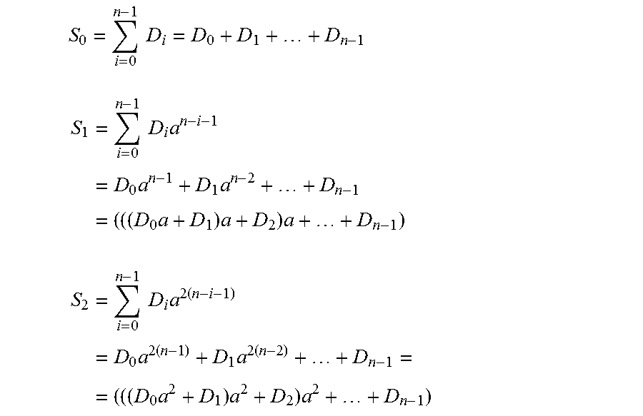
The present invention provides a method for calculating and storing three checksums in a memory to increase the performance and reliability of a storage device. This method allows recovery of a greater number of simultaneously failed parts of the storage device and also provides data recovery in case of data corruption. The method allows for data recovery when up to three simultaneous failures arise and can recover both read and write errors that are not registered by the hardware. The control checksums are calculated using three formulas and the data is restored by using the reference and the current checksums and solving the systems of equations obtained from the formulas of checksums calculating. This method helps to create larger arrays of records in the storage device and overcomes the technical problem of storage element reliability.

Problems solved by technology

However, the known methods may not ensure sufficient reliability for large arrays of stored information due to the parameters of reliability of modern storage devices.
When using a large number of disks, the real risk of failure of two or more disks may appear.
In practice, this risk is overcome by splitting up large arrays into the small, which implies additional expenses to use large amounts of memory to store the checksums.

Method used


Image

  • Method for Recovering Recordings in a Storage Device and System for Implementing Same
  • Method for Recovering Recordings in a Storage Device and System for Implementing Same
  • Method for Recovering Recordings in a Storage Device and System for Implementing Same

Examples


Embodiment Construction

[0038]The claimed method is implemented as follows. The storage device is characterized by the common amount of memory. To implement this method, the total amount of memory should be split into information zones of the same size, selected from different parts of the storage device, and control zones, selected from different parts of the storage device.

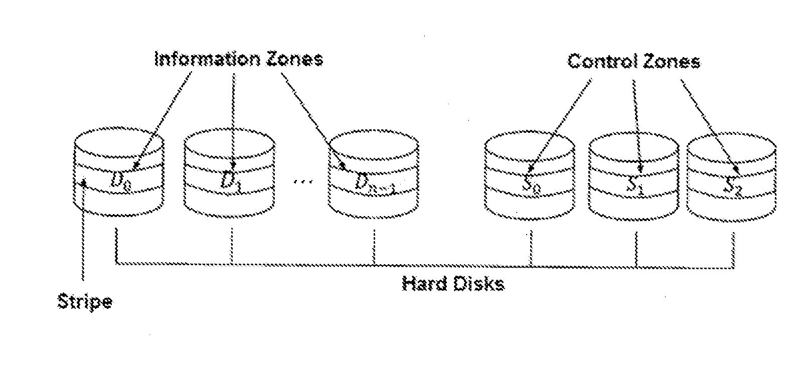
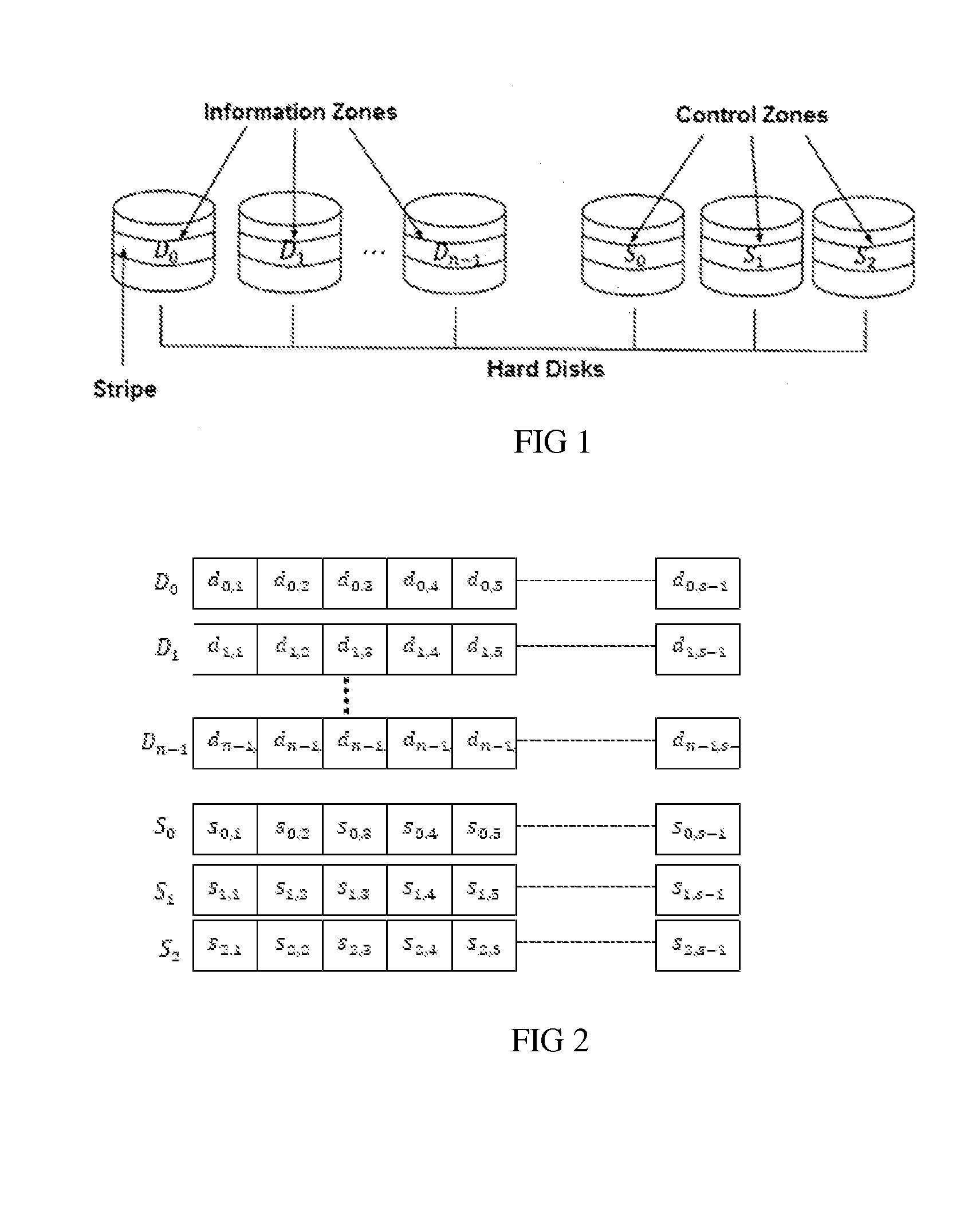
[0039]When a hard disk array is used as a storage device, disks are split into blocks of equal length. The sequence of blocks with the same numbers is located on different disks forms a stripe (FIG. 1). The information zones and the control zones are the blocks of one stripe stored on different disks. Splitting the information zones and the code zones into the areas to store the code words is illustrated in FIG. 2.

[0040]The following detailed description is based on the illustrative example, which demonstrates that the storage device is an array built from the multiple hard drives. The present invention can be also applied to storage d...


PUM


Abstract

The memory of the storage device is divided into information areas of identical size selected from different parts of the storage device, and control zones are selected from different parts of the device. Each group of data is a set of code words written to a corresponding information zone. Three reference control sums S0, S1, S2, each according to a corresponding preset formula, are established by a computation unit. The reference control sums are written as a code word with the same number to a corresponding control zone. If a part of the storage device fails and data becomes corrupted, the current control sums are calculated with the aid of the computation unit. The values of the stored reference control sums and the current control sums are used for recovering lost data. The number of equations depends on the number of failed or faulty zones in the storage device.

Description

RELATED APPLICATIONS[0001]This application is a Continuation application of International Application PCT / RU2013 / 000579, filed on Jul. 9, 2013, which in turn claims priority to Russian Patent Applications No. RU2012140679, filed Sep. 12, 2012, both of which are incorporated herein by reference in their entirety.FIELD OF THE INVENTION[0002]The present invention relates to the systems for detecting and correcting data errors on data carriers, in particular in the case of failure or damage of a part of a storage device or corruption of data on the storage device.BACKGROUND OF THE INVENTION[0003]A key technology to ensure reliability of storing data in the storage device is the ability to recover the data in case of failure of one or more zones of the storage device. At present, most storage devices are used to store large amounts of information, represented as disks arrays, one may consider the possibility of data recovery in case of failure of one or more hard disks. For this, a varie...

Claims


Application Information

Patent Timeline
Patent Type & Authority Applications(United States)
IPC IPC(8): G06F11/10H03M13/15
CPCG06F11/1096G06F11/1068H03M13/152G06F11/1004G11C16/3404G06F11/1076H03M13/134H03M13/15
Inventor MAROV, ALEXEY V.UTESHEV, ALEXEY Y.
Owner RAIDIX
Learn More