
Engine driven heat pump

a heat pump and engine technology, applied in the direction of machines using waste heat, refrigerating machines, lighting and heating apparatus, etc., can solve the problem of not being able to disclose any specific information

Inactive Publication Date: 2015-07-02
YANMAR POWER TECHNOLOGY CO LTD
View PDF9 Cites 7 Cited by
  • Summary
  • Abstract
  • Description
  • Claims
  • Application Information

AI Technical Summary

Benefits of technology

This patent describes a heat pump system that uses less power than an outdoor fan, which is the engine cooling water pump. Additionally, it explains how the heat pump system can operate when there is no power available. This allows for more efficient and effective operation in case of power failures.

Problems solved by technology

However, Japanese Patent No. 4682558 discloses that the engine driven heat pump, in which the generator is mounted, is used as the power supply device at the time of power failure, Japanese Patent No. 4682558 fails to disclose any specific timing of supplying power to an internal instrument that is provided in the engine driven heat pump and driven by the generation power of a generator, at the start time of a self-sustaining operation.

Method used


Image

  • Engine driven heat pump
  • Engine driven heat pump
  • Engine driven heat pump

Examples


Embodiment Construction

[0020]Hereinafter, the embodiment of the present invention will be described referring to drawings.

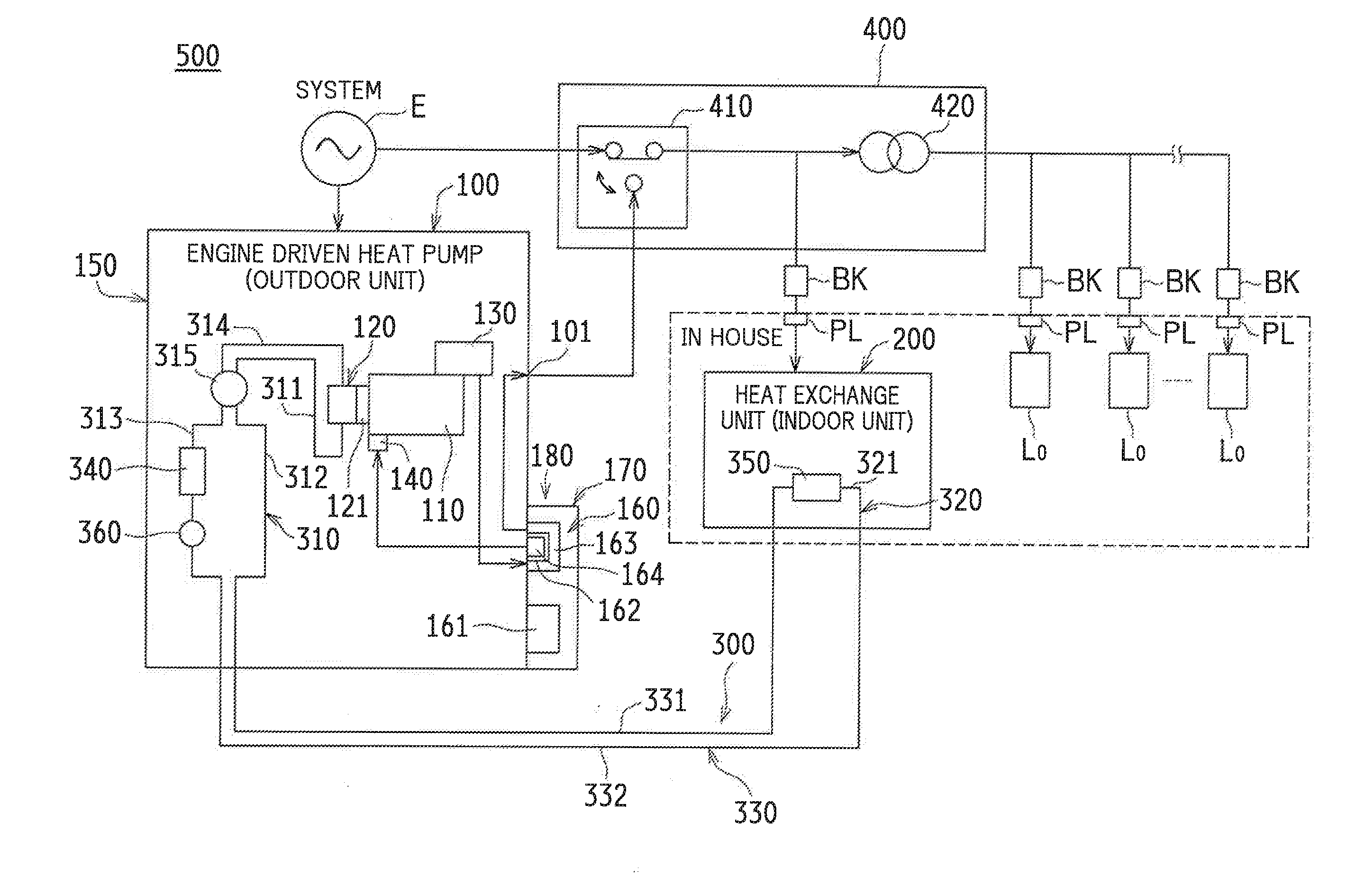
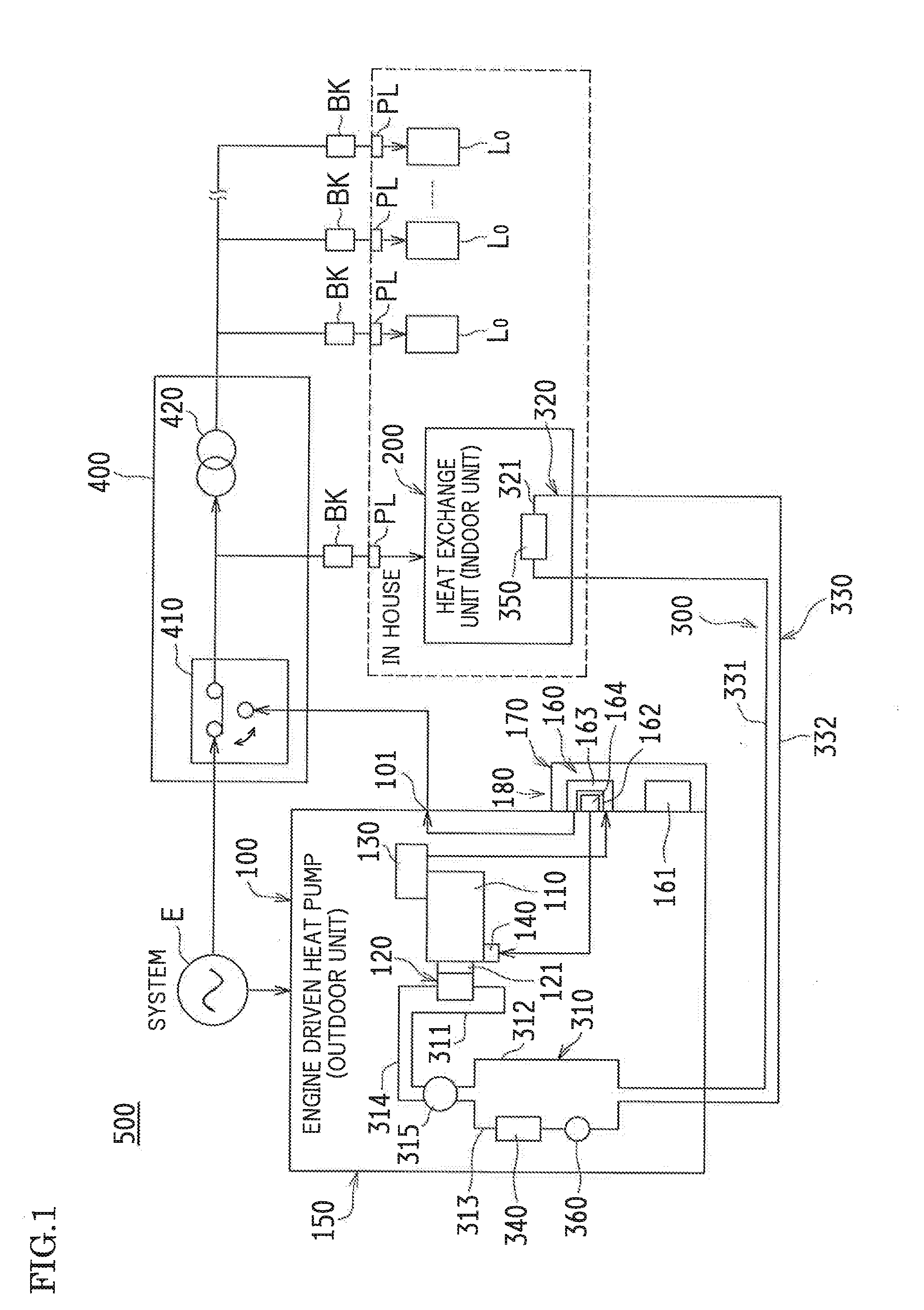
[0021]FIG. 1 is a schematic block diagram illustrating one example of a heat exchange system 500 including an engine driven heat pump 100 according to the embodiment of the present invention.

[0022]The heat exchange system 500 illustrated in FIG. 1 is provided in such a manner that a refrigerant is circulated through a refrigerant circulation path 300 while a state where the refrigerant is decompressed and brought down to a low temperature and a state where the refrigerant is pressurized and brought up to a high temperature are alternated by means of the engine driven heat pump 100.

[0023]The refrigerant circulation path 300 includes a first refrigerant circuit 310 (one example of a refrigerant circuit) provided in the engine driven heat pump 100 (an outdoor unit constituting an air conditioner in the example), a second refrigerant circuit 320 provided in a heat exchange unit 200 (an ind...


PUM


Abstract

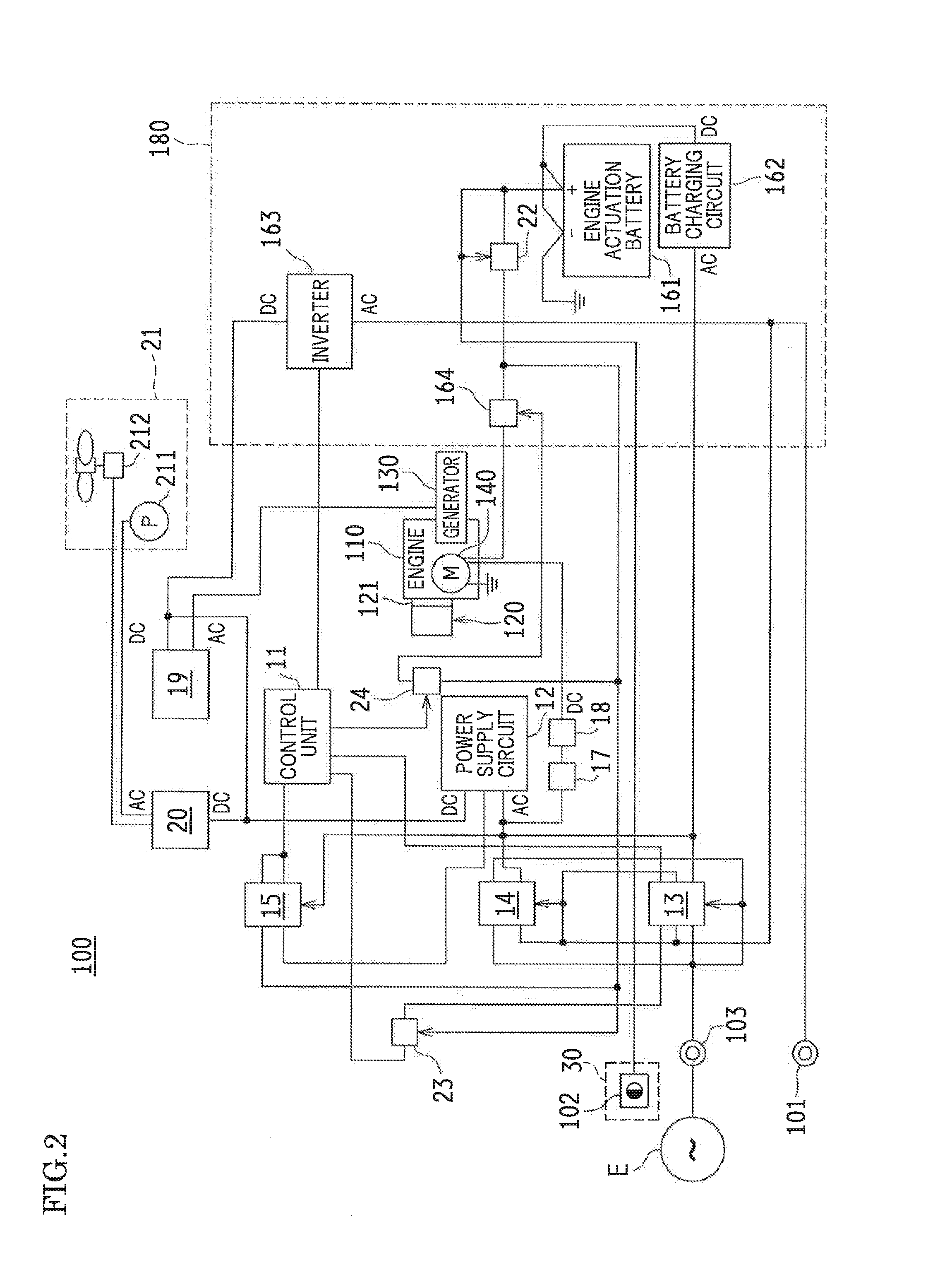
An engine driven heat pump includes an outdoor fan and an engine cooling water pump, each of which is driven by the generation power of a generator, and after a lapse of a first predetermined time from a predetermined actuation time of an engine, the output power from the generator is output-controlled, and the power output control is started so as to obtain the generation power, and when it is determined that the generation voltage after the start of the power output control is equal to or higher than a predetermined voltage, the engine cooling water pump is driven, and after a lapse of a second predetermined time from a predetermined drive time of the engine cooling water pump, the outdoor fan is driven, and after a lapse of a third predetermined time from a predetermined drive time of the outdoor fan, the output control of the inverter is started.

Description

[0001]This nonprovisional application claims priority under U.S.C. 119(a) on Patent Application No. 2013-272908 filed in Japan on Dec. 27, 2013, the entire contents of which are hereby incorporated by reference.BACKGROUND OF THE INVENTION[0002]1. Field of the Invention[0003]The present invention relates to an engine driven heat pump in which heat exchange is performed by use of a refrigerant, which is sucked and discharged by a compressor driven by an engine, thereby flowing through a refrigerant circuit.[0004]2. Description of the Related Art[0005]Conventionally, it has been known that a generator is mounted in the engine driven heat pump in which heat exchange is performed by use of a refrigerant, which is sucked and discharged by a compressor driven by the engine, thereby flowing through a refrigerant circuit (see, for example, Japanese Patent No. 4682558).[0006]Japanese Patent No. 4682558 discloses that the engine driven heat pump, in which the generator is mounted, is used as a...

Claims


Application Information

Patent Timeline
Patent Type & Authority Applications(United States)
IPC IPC(8): F25B27/02
CPCF25B27/02
Inventor OKADA, HIDESHIHASHIMOTO, KYOKO
Owner YANMAR POWER TECHNOLOGY CO LTD
Learn More