
Eureka
For R&D, Eureka makes reading and utilizing patents & technical documents easy.
Eureka AIR
Designed for self-driven R&D workflows. Generate viable solutions, solve complex R&D challenges, empower your innovation with AI.

Eureka Materials
Designed for material experts only. Revolutionize your material R&D, from search, analyze, to developing new materials.

TechResearch
Generate reliable direction feasibility study reports for your R&D in just a few steps.

TechSeek
Discover and master advanced knowledge NOW. Basics, ideas, possibilities, all at once.

TechMind
As an expert in R&D Theories, TechMind can generates customized viable solutions instantly.

TechRisk
Analyze your overall solution with one click, know your potential R&D risks in advance.

TechMonitor
Get weekly tech updates, stay abreast of the latest tech innovations and key insights.
Image forming apparatus
- Summary
- Abstract
- Description
- Claims
- Application Information
AI Technical Summary
Benefits of technology
Problems solved by technology
Method used
Image

Examples
first embodiment
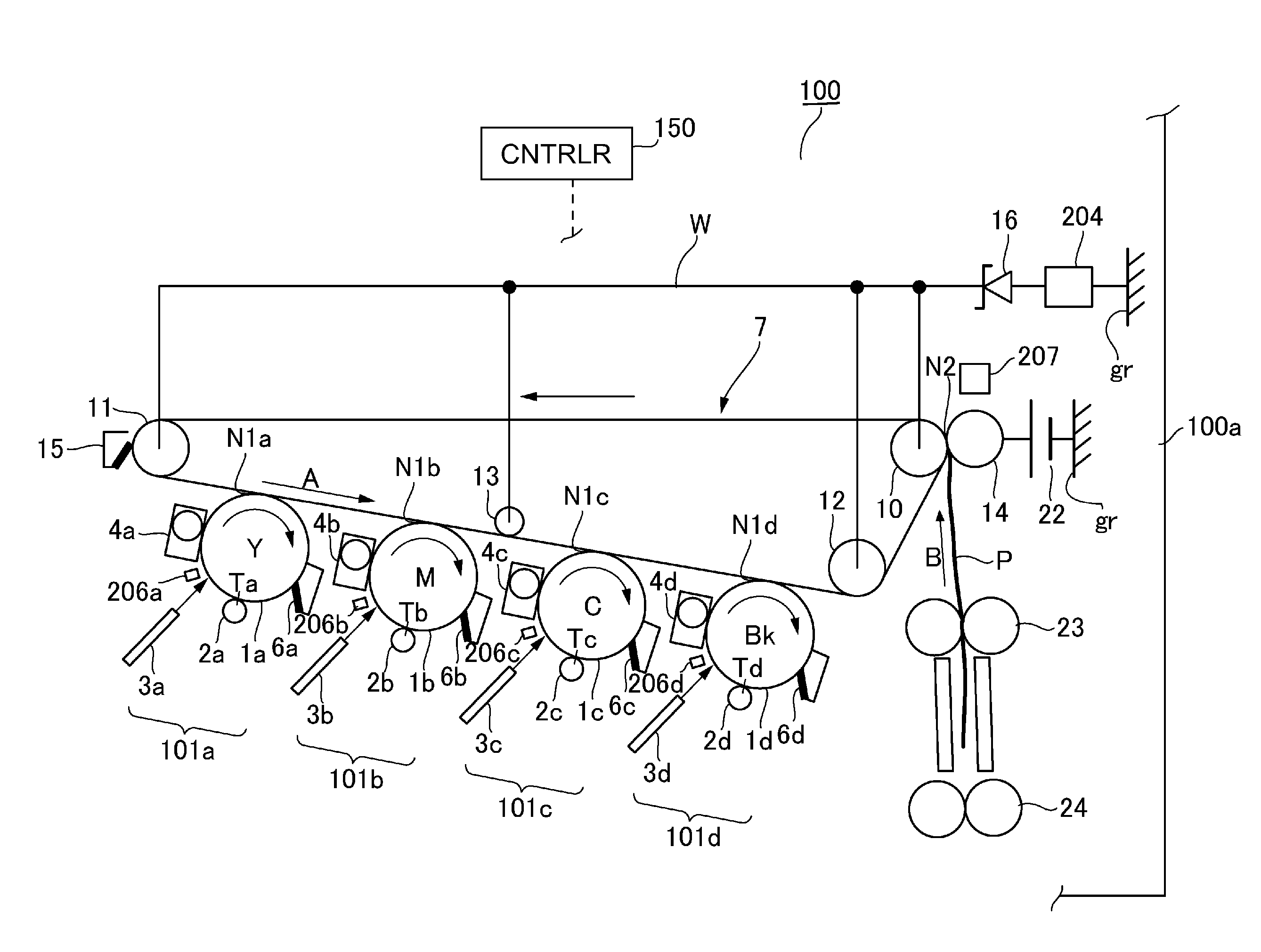
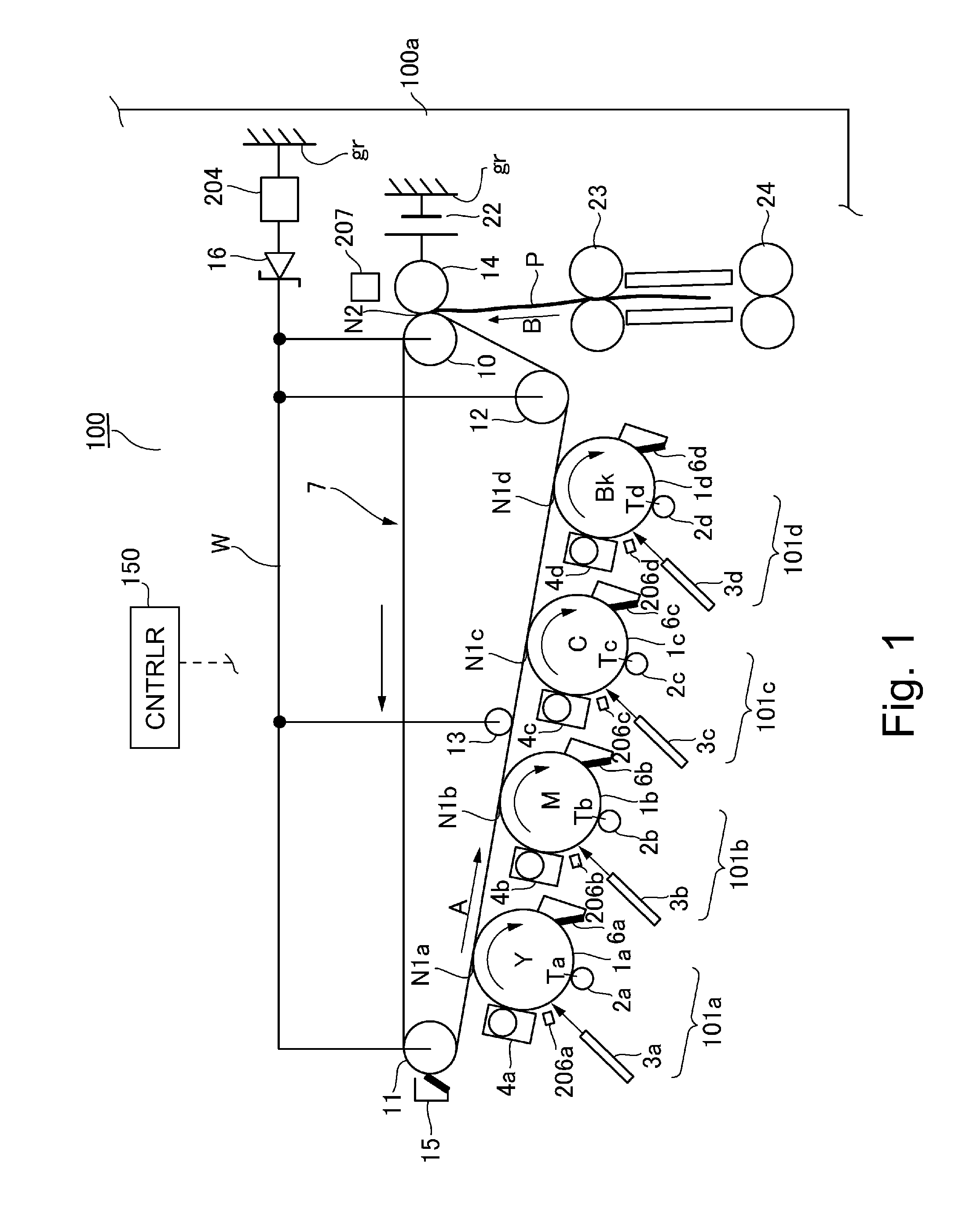
[0023]First, with reference to FIG. 1, an image forming apparatus in this embodiment will be described. That is, as shown in FIG. 1, an image forming apparatus 100 includes an image forming apparatus main assembly 100a. The image forming apparatus 100 is constituted as a full-color printer in which image forming portions (image forming units) 101a, 101b, 101c and 101d for yellow (Y), magenta (M), cyan (C) and black (Bk), respectively, are arranged along a downward surface of an intermediary transfer belt 7 as an intermediary transfer member.
[0024]The image forming apparatus 100 not only employs a tandem type in which image forming units for respective colors are independent and arranged in tandem, but also employs an intermediary transfer type in which toner images are transferred from the image forming units for respective colors onto the intermediary transfer member, and then are transferred from the intermediary transfer member onto a recording material.
[0025]Image forming portio...
second embodiment
[0110]Next, with reference to FIGS. 1, 7 and 8, Second Embodiment according to the present invention will be described. In this embodiment, the constitution of FIG. 1 is similar to that in First Embodiment, but control using the constitution is somewhat different from that in First Embodiment.
[0111]FIG. 7 is an illustration of switching of the charging high voltage (DC component) in this embodiment, and (a) and (b) of FIG. 8 are timing charts in this embodiment. The same members as those in First Embodiment are represented by the same reference numerals or symbols, and the members having the same constitutions and functions as those in First Embodiment will be omitted from description.
[0112]In First Embodiment, in the case where the trailing end weak bias control was carried out, the control was effected in the following manner. That is, the controller 150 increased the sheet interval distance during the continuous sheet passing so that the image forming operation at the primary tra...
third embodiment
[0129]Next, with reference to FIGS. 9, 10 and 11, Third Embodiment according to the present invention will be described. FIG. 9 is a schematic view for illustrating a basic structure of an image forming apparatus 100 in this embodiment. FIG. 10 is an illustration of switching of a charging high voltage (DC component) in this embodiment, and FIG. 11 is an illustration of switching of a charging high voltage (DC component) in this embodiment. The same members as those in First Embodiment are represented by the same reference numerals or symbols, and the members having the same constitutions and functions as those in First Embodiment will be omitted from description.
[0130]As shown in FIG. 9, the image forming apparatus 100 is constituted as an intermediary transfer type full-color printer of a tandem type in which image forming portions (image forming units) 101a, 101b, 101c and 101d for yellow (Y), magenta (M), cyan (C) and black (Bk), respectively, are arranged along an upward surfac...
PUM
 Abstract
Description
Claims
Application Information
 - R&D Engineer
- R&D Manager
- IP Professional
- Industry Leading Data Capabilities
- Powerful AI technology
- Patent DNA Extraction
Browse by: Latest US Patents, China's latest patents, Technical Efficacy Thesaurus, Application Domain, Technology Topic, Popular Technical Reports.
© 2024 PatSnap. All rights reserved.Legal|Privacy policy|Modern Slavery Act Transparency Statement|Sitemap|About US| Contact US: help@patsnap.com