Touch pad input device
a technology of input device and touch pad, which is applied in the field of touch pad input device, can solve the problems of increasing the footprint of the input device b>, affecting the miniaturization of an electronic apparatus, etc., and achieves the effect of increasing the number of parts
- Summary
- Abstract
- Description
- Claims
- Application Information
AI Technical Summary
Benefits of technology
Problems solved by technology
Method used
Image

Examples
first embodiment
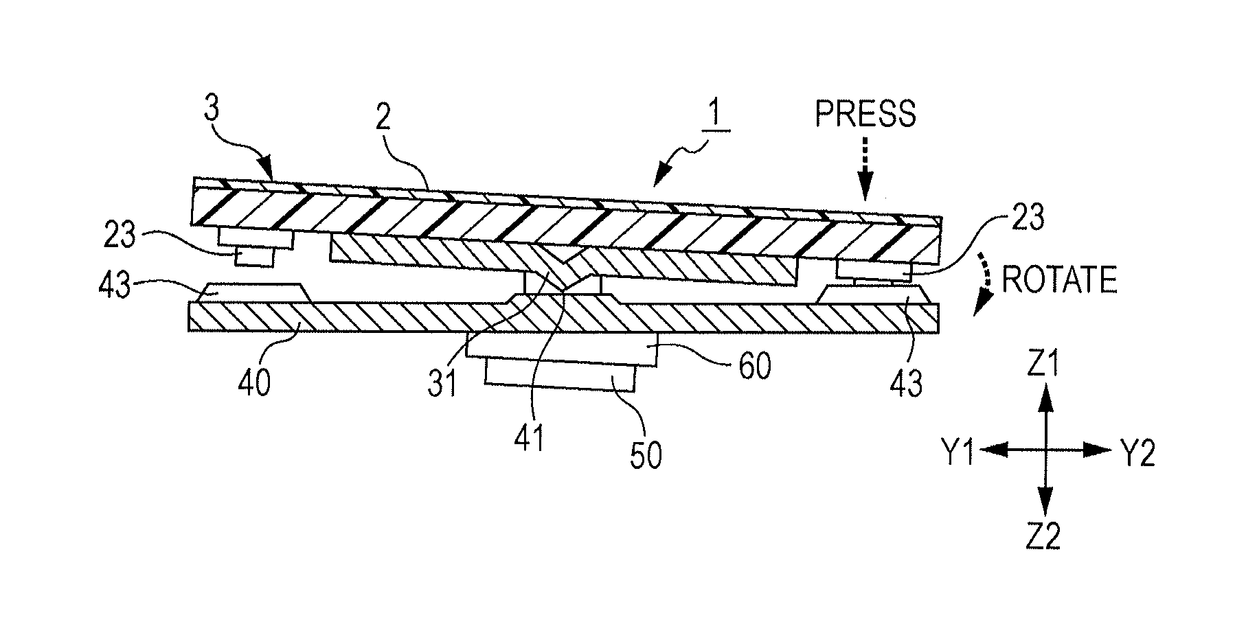
[0047]A first embodiment of the present invention will be described with reference to the drawings. In the drawings, X1 denotes a leftward direction, X2 denotes a rightward direction, Y1 denotes a forward direction, Y2 denotes a backward direction, Z1 denotes an upward direction, and Z2 denotes a downward direction.
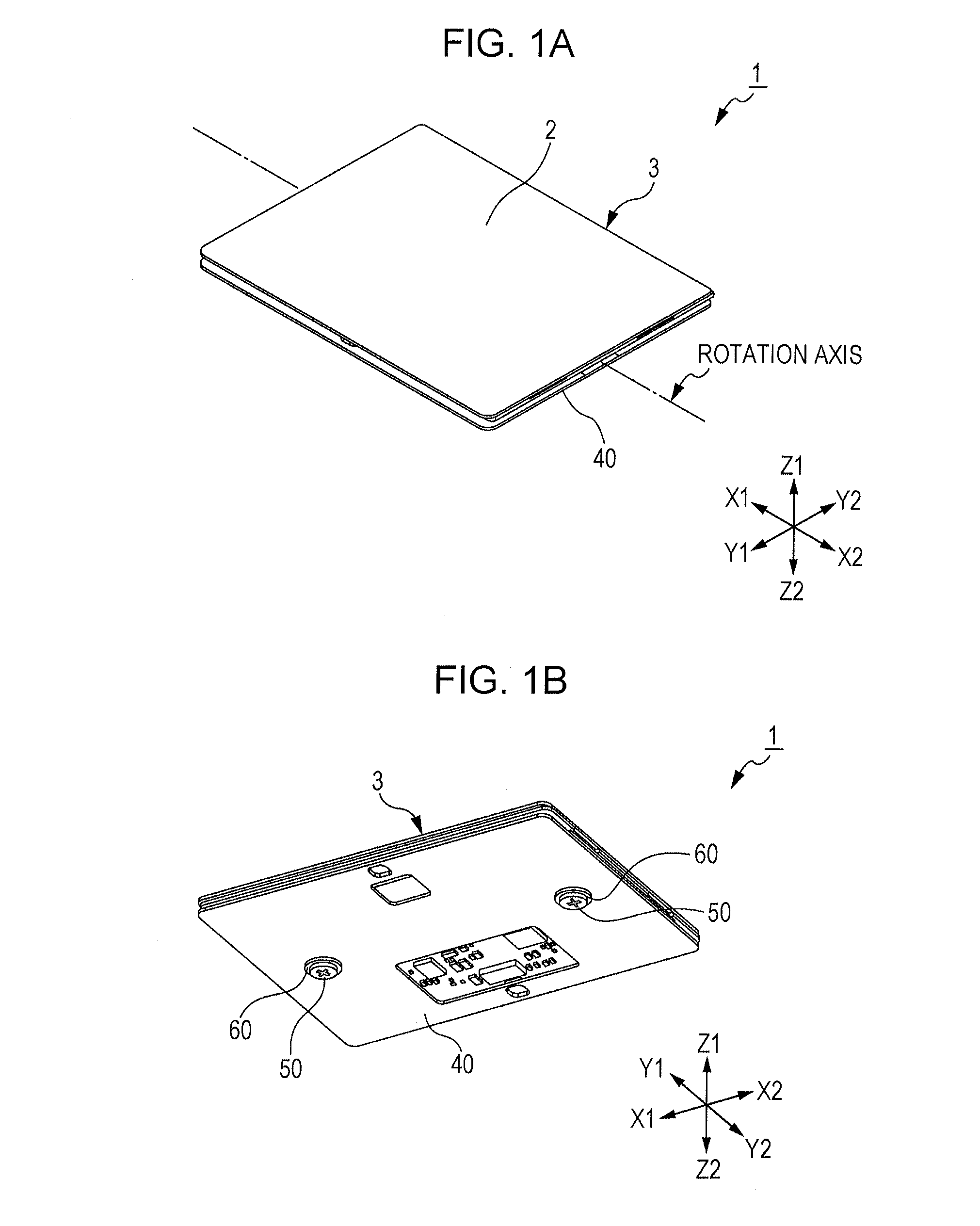
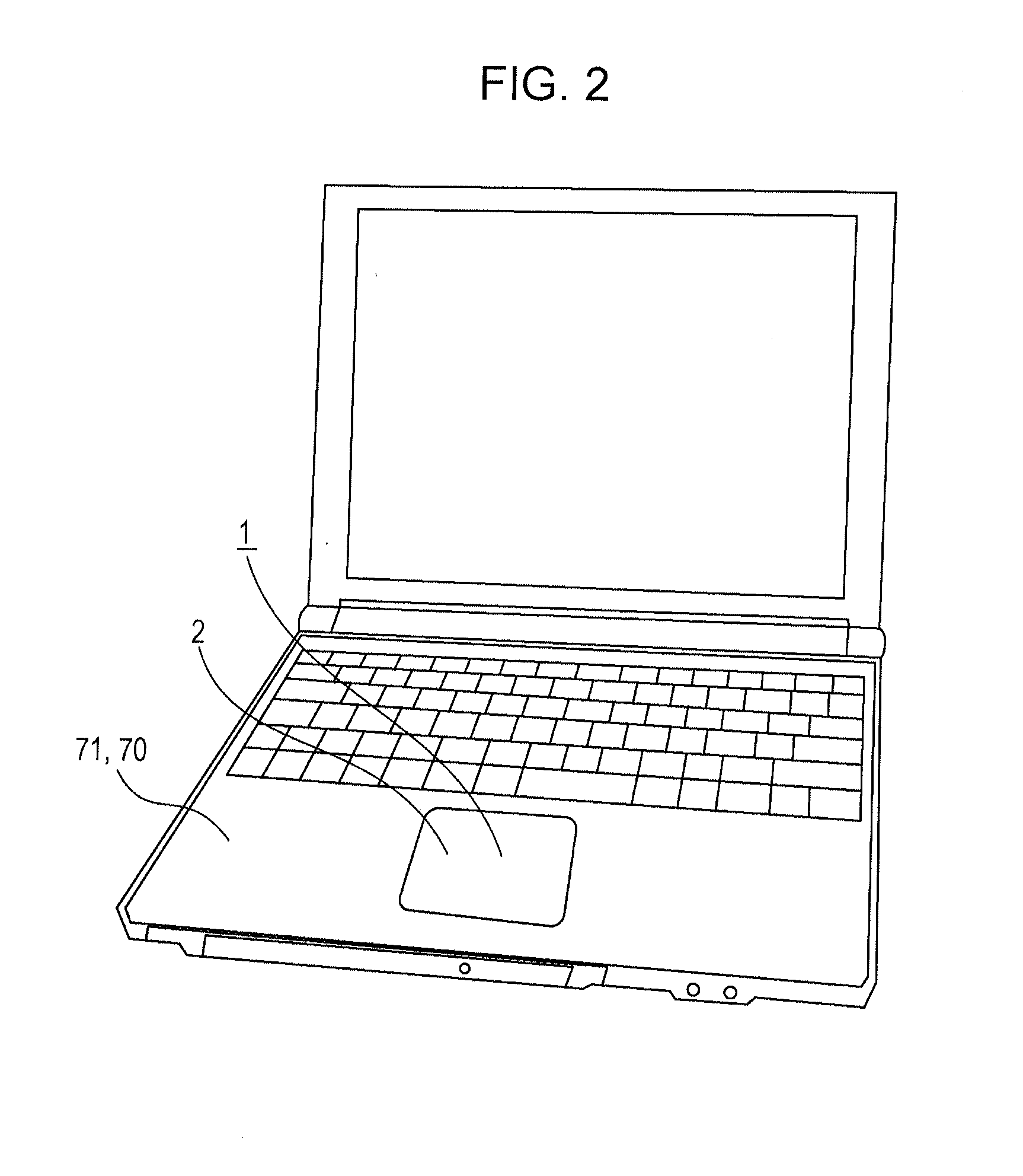
[0048]The configuration of a touch pad input device 1 according to the first embodiment of the present invention will now be described with reference to FIGS. 1A to 6B. FIGS. 1A and 1B are diagrams illustrating the configuration of the touch pad input device 1 according to the first embodiment. FIG. 1A is a perspective view of the touch pad input device 1 when viewed from above. FIG. 1B is a perspective view of the touch pad input device 1 when viewed from below. FIG. 2 is a diagram illustrating an example of use of the touch pad input device 1 illustrated in FIGS. 1A and 1B. FIG. 3 is an exploded perspective view of the touch pad input device 1 illustrated in FIG. 2 when...
second embodiment
[0086]A second embodiment of the present invention will be described below with reference to the drawings. In the description of the second embodiment, the same components as those in the first embodiment are designated by the same reference numerals and a detailed description of the previously described components is omitted.
[0087]The configuration of a touch pad input device 101 according to the second embodiment of the present invention will now be described with reference to FIGS. 10A and 10B. FIGS. 10A and 10B are diagrams illustrating the configuration of the touch pad input device 101 according to the second embodiment. FIG. 10A is a schematic view of the touch pad input device 101 when viewed from above. FIG. 10B is a schematic cross-sectional view of the touch pad input device 101 taken along the line XB-XB in FIG. 10A.
[0088]As illustrated in FIGS. 10A and 10B, the touch pad input device 101 includes a touch pad (movable element) 3 having an operation surface 2, serving as ...
third embodiment
[0095]A third embodiment of the present invention will be described below with reference to the drawings. In the description of the third embodiment, the same components as those in the first embodiment are designated by the same reference numerals and a detailed description of the previously described components is omitted.
[0096]The configuration of a touch pad input device 201 according to the third embodiment of the present invention will now be described with reference to FIGS. 11A and 11B. FIGS. 11A and 11B are diagrams illustrating the configuration of the touch pad input device 201 according to the third embodiment. FIG. 11A is a schematic view of the touch pad input device 201 when viewed from above. FIG. 11B is a schematic cross-sectional view of the touch pad input device 201 taken along the line XIB-XIB in FIG. 11A.
[0097]As illustrated in FIGS. 11A and 11B, the touch pad input device 201 includes a touch pad (movable element) 3 having an operation surface 2, serving as an...
PUM
 Abstract
Description
Claims
Application Information
 - R&D
- Intellectual Property
- Life Sciences
- Materials
- Tech Scout
- Unparalleled Data Quality
- Higher Quality Content
- 60% Fewer Hallucinations
Browse by: Latest US Patents, China's latest patents, Technical Efficacy Thesaurus, Application Domain, Technology Topic, Popular Technical Reports.
© 2025 PatSnap. All rights reserved.Legal|Privacy policy|Modern Slavery Act Transparency Statement|Sitemap|About US| Contact US: help@patsnap.com