Mechanical Latching Relays and Hybrid Switches with Latching Relays for Use in Electrical Automation

a technology of latching relay and hybrid switch, which is applied in the direction of electromagnetic relay details, electrical apparatus, sustainable buildings, etc., can solve the problems of electrical power consumption, large overall consumption of power, and use of many relays

Active Publication Date: 2015-07-02
ELBEX VIDEO LTD
View PDF1 Cites 22 Cited by
  • Summary
  • Abstract
  • Description
  • Claims
  • Application Information

AI Technical Summary

Benefits of technology

[0018]Another practical objective attained by the present invention is to provide the hybrid switch with a structure that can be fitted with different key levers and the freedom to select any from the wide variety of levers and decorative covers and frames including variety of design and colors that are available and are being regularly introduced to the construction / electrical industry by the different switches manufacturers. Hence, this invention solves the difficulties experienced to match such wide range of available AC switch designs, their panel colors and decorations.
[0024]Chain connected SPDT and DPDT switches of a home automation system of the prior art made it impossible to identify the on-off status of the appliance such as light fixture, unless the data of all the switches and relays status of a given circuit are transmitted to the controller. This mandates the recording and updating of all the manual switch's positions and the relay's data to the controller. This presents a complicated data handling and ensuing operational complications, requiring the transmitting of all the data every time a manual switch or relay is activated at random in the system, and this in return introduces substantial more data traffic and processing.
[0039]This movement causes movement between the two contacts, the pole contact and the contactor contact. The movement can provide a brushing effect by cleaning electrical blemishes from the surface of the contacts, but such movement also may create contact pressure variations which must be minimized to ensure that current carrying capacity is not affected by the inter contact movements.

Problems solved by technology

Another problem affecting the electrical power consumption is the use of many relays that consume power for self-operating and control.
Many relays installed in a residence or in a shop, or in a factory, or in public facilities persistently drain current and consumed power, thus when many such automation system are installed the overall consumed power will be substantial.
Latching power relays, using dual magnetized armatures or poles or other structured magnetic element are expensive and requiring complex circuitry and programming to control.

Method used


Image

  • Mechanical Latching Relays and Hybrid Switches with Latching Relays for Use in Electrical Automation
  • Mechanical Latching Relays and Hybrid Switches with Latching Relays for Use in Electrical Automation
  • Mechanical Latching Relays and Hybrid Switches with Latching Relays for Use in Electrical Automation

Examples


Embodiment Construction

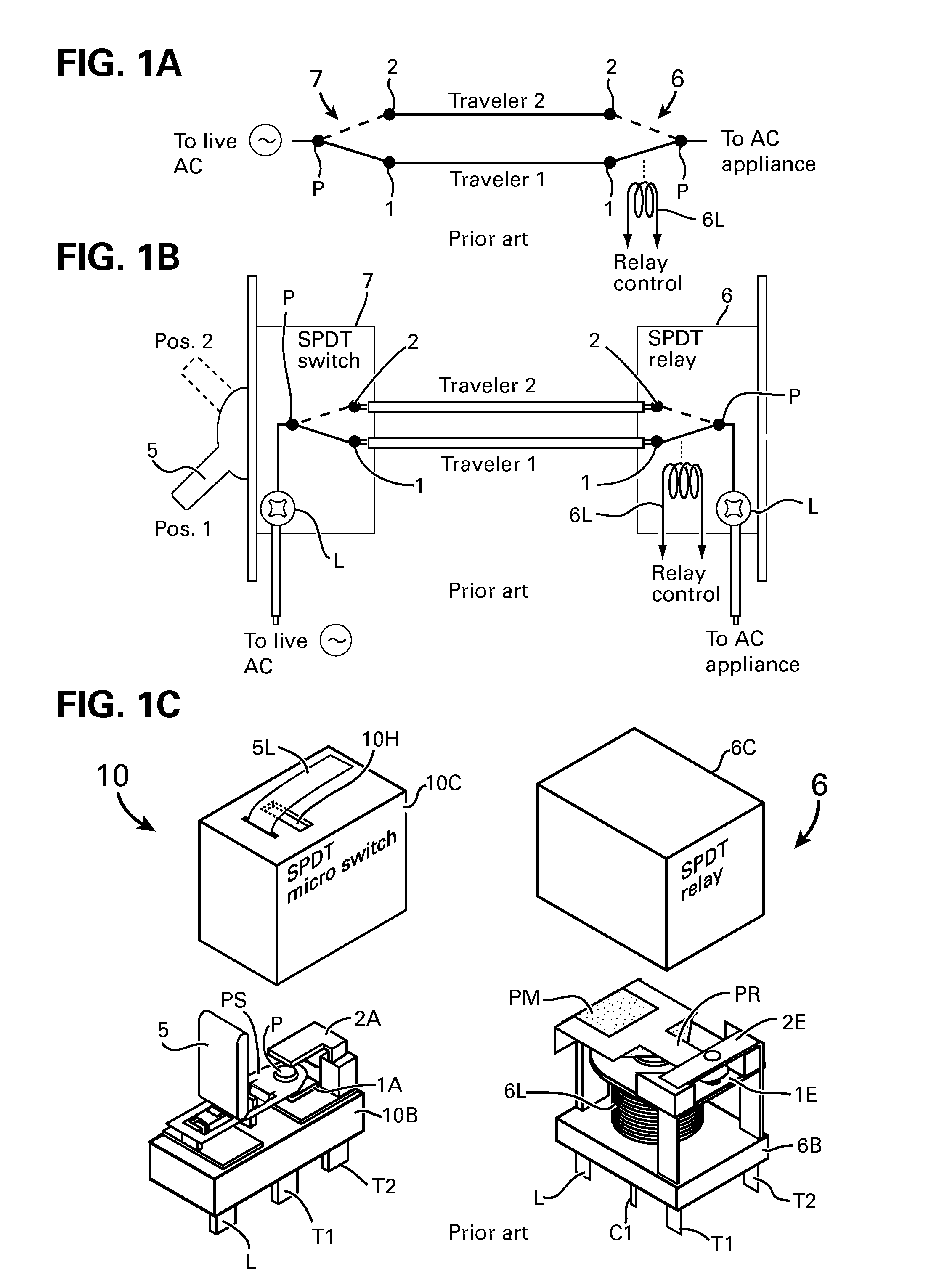
[0080]FIG. 1A Shows an electrical circuit comprising a single pole double throw (SPDT) AC switch 7 connected to an automation SPDT relay 6 operated by a relay coil 6L of the prior art such as disclosed in the U.S. Pat. No. 7,649,727. The circuit is a variation of a well known circuit for connecting two traveler wires between two traveler terminals 1 and 2 of two SPDT AC switches for switching on-off lights from two distinct places within the premises, such as switching a corridor's light from two ends of the corridor. The SPDT switches are also known as two-way switches, and are well established for many years.

[0081]The prior art combination of SPDT switch 7 and the SPDT relay 6 shown in FIG. 1B were introduced in the reference U.S. Pat. No. 7,649,727 and other referenced US patents, reciting a new electrical automation concept for simplifying the electrical home automation wiring in residential and other buildings. The combination of SPDT switch and SPDT relay enabled to maintain t...


PUM


Abstract

Method and apparatus for a mechanical latching of at least one pole of a relay selected from SPST, SPDT, DPDT, reversing DPDT, multi pole MPST and MPDT including the integration of one of a single and plurality of hybrid SPDT or DPDT switches with one of SPDT and DPDT mechanically latching relay using springy element to maintain the contacts between the poles and one of the relay contact and a structured contactors to connect the poles of the relay and the switch including PCB assembly, for operating electrical loads via the switch manual key including the introduction of a key-plunger combination into the latching relay and remotely by powering the relay coil by a power pulse, including a CPU program for providing any of the manual keys of each SPDT or DPDT connected in a traveler lines to the integrated switch-relay to switch on-off group of loads and all the loads of home automation network or grid via optical cable, RF, IR in line of sight and bus line.

Description

BACKGROUND OF THE INVENTION[0001]1. Field of the Invention[0002]This invention is related to electrical automation devices including switches and relays for manual and remote operation of appliances in residences and other buildings.[0003]2. Description of the Prior Art[0004]Switches and relays for switching on-off electrical appliances such as water boiler, air conditioners, heaters, lights and any other electrical equipment and appliances in residences, offices, public building, businesses, restaurants and factories are very well known. The well known relay devices for home automation are commonly installed in the main or a sub electrical cabinet of a given premises. The installed relays are operated via bus lines, RF, or by control signal propagated via the AC power line.[0005]The costs of the prior known automation devices and relays including their installation are very high because the electrical wiring must be changed from its standard commonly applied wiring systems, in whic...

Claims


Application Information

Patent Timeline
Patent Type & Authority Applications(United States)
IPC IPC(8): H01H51/27
CPCH01H51/27H01H9/167H01H9/26H01H47/22H01H89/00H01H2300/03Y04S20/14H01H13/562H01H51/10Y02B90/20H01H29/00H01H50/02H01H50/14H01H50/326H01H50/443H01H50/58
Inventor ELBERBAUM, DAVID
Owner ELBEX VIDEO LTD
Why Eureka
Try Eureka