Integrated spdt or dpdt switch with spdt relay combination for use in residence automation

a technology of integrated spdt or dpdt switch and relay combination, which is applied in the direction of air break switch, relay, sustainable building, etc., can solve the problems of high cost of prior known automation device and relay including their installation, serious repeated malfunction of the installed electrical automation system, and complex fundamental basic change in the structured electrical system

Active Publication Date: 2015-04-09
ELBEX VIDEO LTD
View PDF4 Cites 28 Cited by
  • Summary
  • Abstract
  • Description
  • Claims
  • Application Information

AI Technical Summary

Benefits of technology

[0012]The main object of the present invention therefore is to provide for a small size combination of SPDT or DPDT switch, an SPDT relay and power consumption measuring and reporting circuit, constructed to be similar to a shape and a size of a commonly used AC switch, referred to hereafter as a “sta

Problems solved by technology

The costs of the prior known automation devices and relays including their installation are very high because the electrical wiring must be changed from its standard commonly applied wiring systems, in which the electrical power is fed via the commonly installed switches in the electrical wall boxes.
Such fundamental basic change in the structured electrical systems became

Method used


Image

  • Integrated spdt or dpdt switch with spdt relay combination for use in residence automation
  • Integrated spdt or dpdt switch with spdt relay combination for use in residence automation
  • Integrated spdt or dpdt switch with spdt relay combination for use in residence automation

Examples


Embodiment Construction

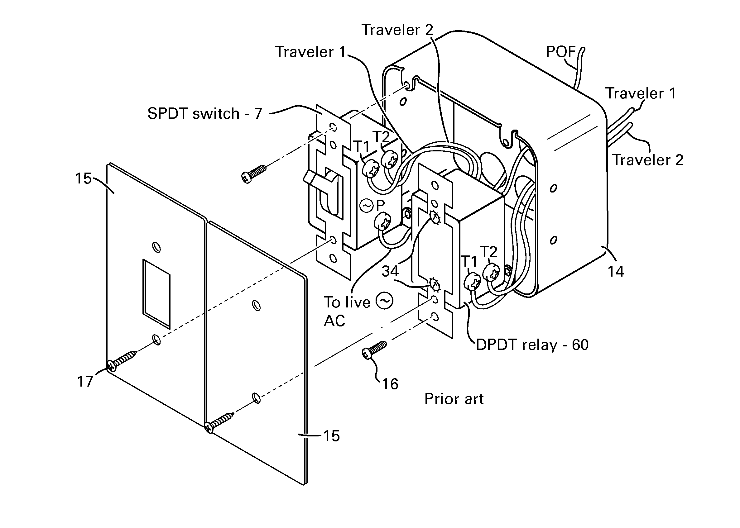
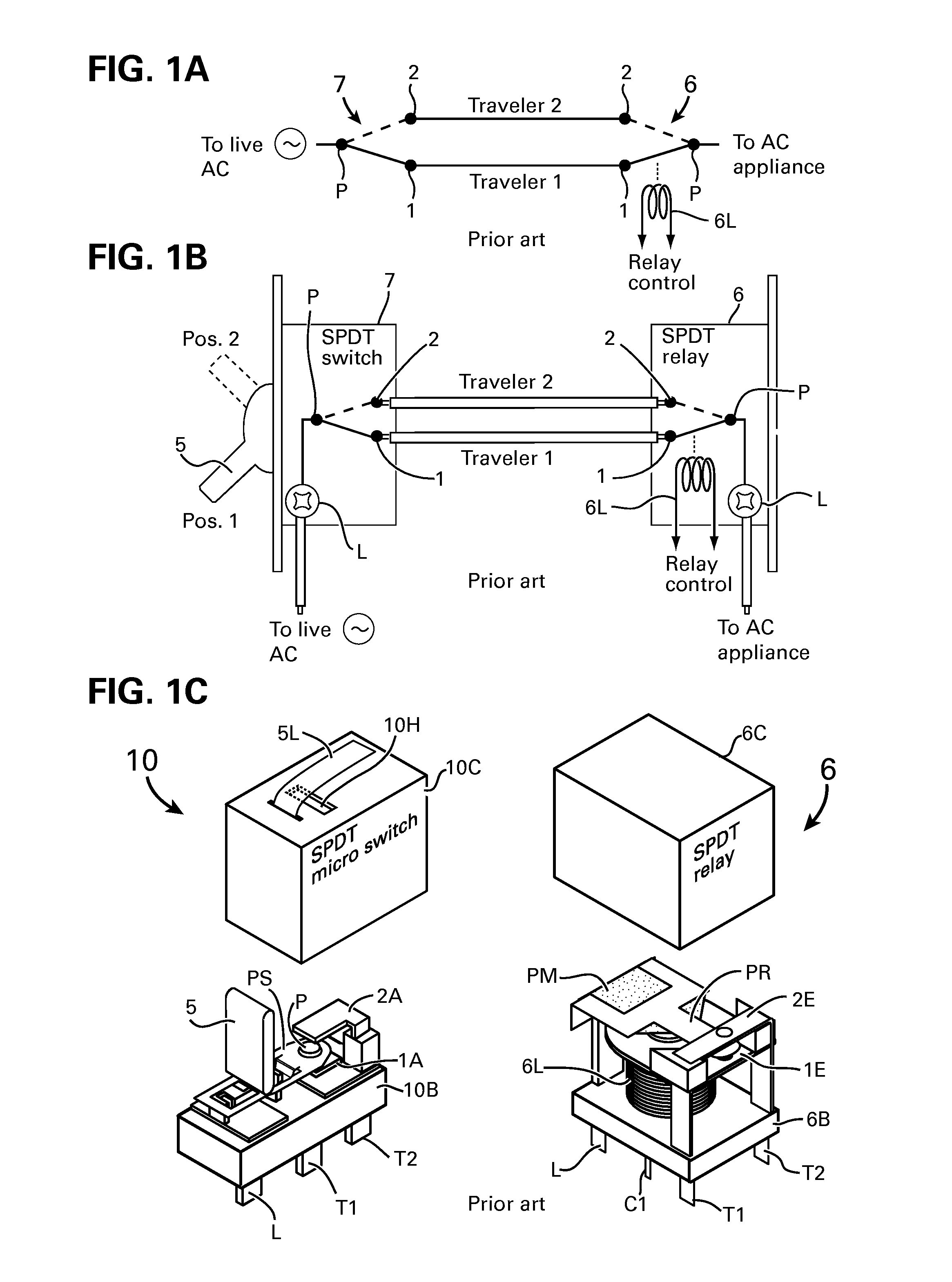
[0059]FIG. 1A Shows an electrical circuit comprising a single pole double throw (SPDT) AC switch 7 connected to an automation SPDT relay 6 operated by a relay coil 6L of the prior art such as disclosed in the U.S. Pat. No. 7,649,727. The circuit is a variation of a well known circuit for connecting two traveler wires between two traveler terminals 1 and 2 of two SPDT AC switches for switching on-off lights from two distinct places within the premises, such as switching a corridor's light from two ends of the corridor. The SPDT switches are also known as two-way switches, and are well established for many years.

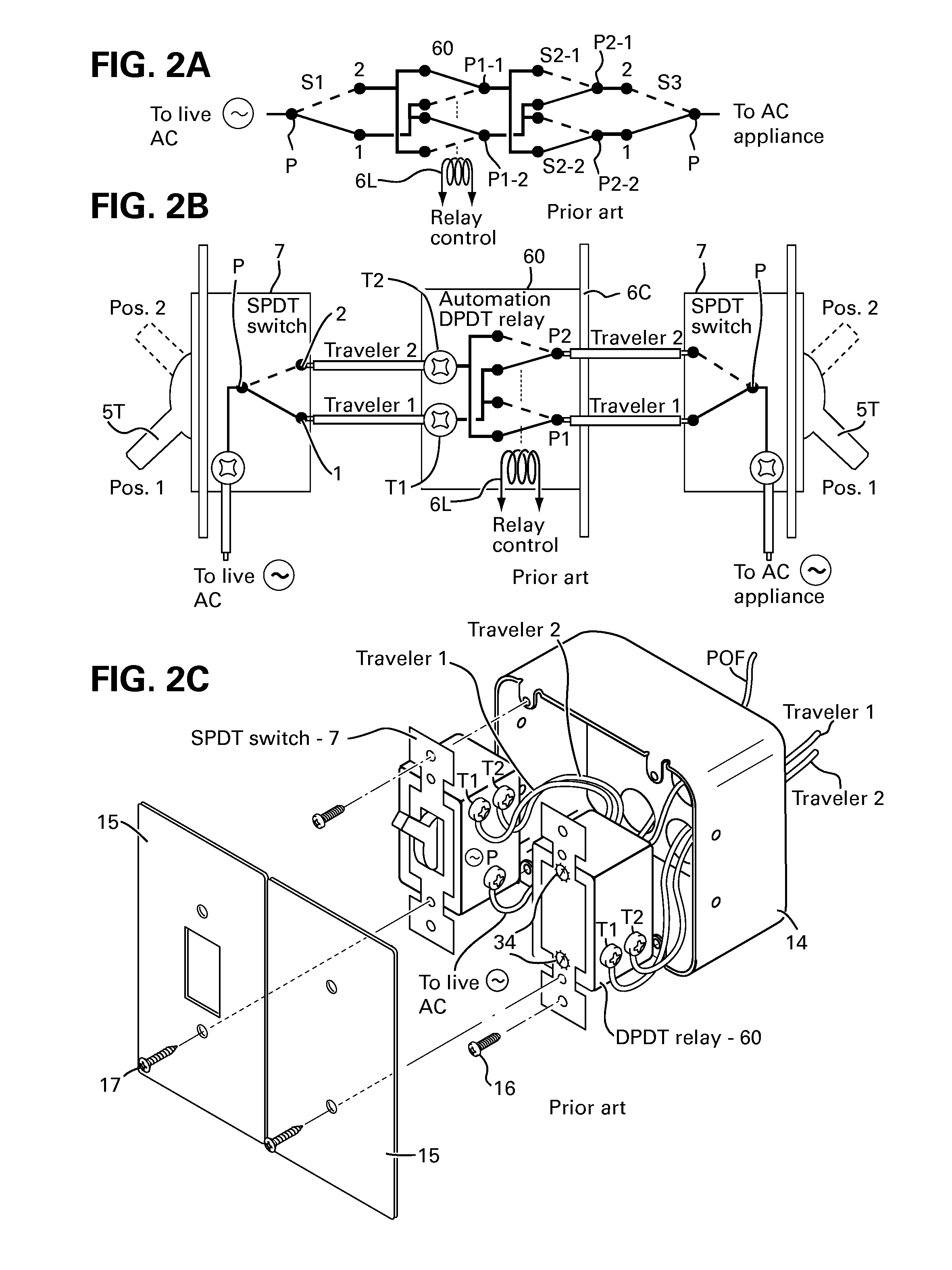
[0060]The prior art combination of SPDT switch 7 and the SPDT relay 6 shown in FIG. 1B were introduced in the reference U.S. Pat. No. 7,649,727 and other referenced US patents, reciting a new electrical automation concept for simplifying the electrical home automation wiring in residential and other buildings. The combination of SPDT switch and SPDT relay enabled to maintain t...


PUM

PropertyMeasurementUnit
Poweraaaaaaaaaa
Sizeaaaaaaaaaa

Abstract

Method and apparatus for integrating one of single and plurality of hybrid SPDT or DPDT switch with one of SPDT and DPDT relay via contactors structured to connect the poles of the relay and the switch directly or via conductive structures including PCB assembly, for operating electrical appliances via the switch manual key and remotely by powering the relay coil having latching or non-latching armature, with a CPU program providing the manual key and the manual keys of each SPDT or DPDT connected in a traveler lines to the integrated switch-relay to switch on-off group of loads and all the loads of home automation network or grid via optical cable, RF, IR in line of sight and bus line.

Description

BACKGROUND OF THE INVENTION[0001]1. Field of the Invention[0002]This invention is related to electrical automation devices including switches and relays for manual and remote operation of appliances in residences and other buildings.[0003]2. Description of the Prior Art[0004]Switches and relays for switching on-off electrical appliances such as water boiler, air conditioners, heaters, lights and any other electrical equipment and appliances in residences, offices, public building, businesses, restaurants and factories are very well known. The well known relay devices for home automation are commonly installed in the main or a sub electrical cabinet of a given premises. The installed relays are operated via bus lines, RF, or by control signal propagated via the AC power line.[0005]The costs of the prior known automation devices and relays including their installation are very high because the electrical wiring must be changed from its standard commonly applied wiring systems, in whic...

Claims


Application Information

Patent Timeline
IPC IPC(8): H01H9/00H01H11/00
CPCH01H9/00H01H11/00Y10T307/747Y10T29/49105H02G3/12Y02B90/224H01H9/167H01H89/00H01H2300/03Y04S20/14H02G3/14Y02B90/20H01H9/0027
Inventor ELBERBAUM, DAVID
Owner ELBEX VIDEO LTD
Why Eureka
Try Eureka