
Apparatus for controlling fuel cell heating value

Active Publication Date: 2015-07-02
SK INNOVATION CO LTD
View PDF0 Cites 0 Cited by
  • Summary
  • Abstract
  • Description
  • Claims
  • Application Information

AI Technical Summary

Benefits of technology

The present invention provides an apparatus and method for controlling the heating value of fuel cell stacks or modules that are connected to each other. The invention minimizes the deviation in heating values between the stacks or modules, which helps prevent deterioration, degradation, and shut down of the stacks. The invention allows for the heating values to be controlled by the user, making it convenient for them. Overall, the invention improves the reliability and efficiency of fuel cell stacks or modules and enhances user experience.

Problems solved by technology

However, if stacks or stack modules deteriorate at different rates, a deviation in the performance between the stacks or stack modules is caused as operating time passes.
Furthermore, when the efficiency of some stacks is lowered due to abnormal acceleration of deterioration, a deviation in the performance between the stacks or stack modules is also induced.
Alternatively, the stacks or stack modules may not be uniform in performance from production, so that a performance deviation may be present from beginning of operation.
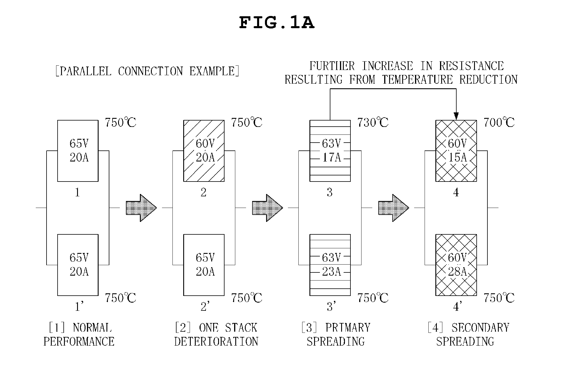
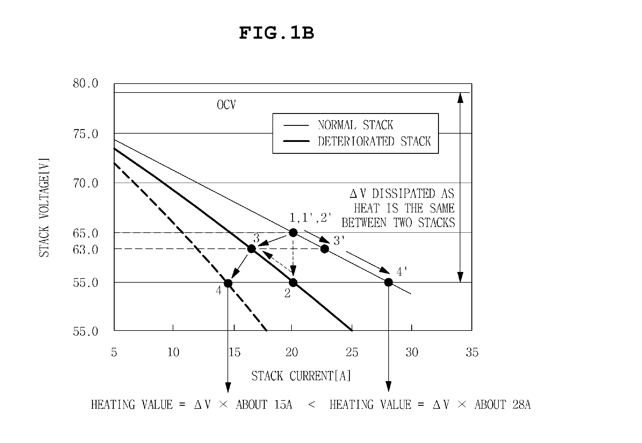
Moreover, when a performance deviation occurs, heating values of the stacks or stack modules differ from each other, and a deviation in temperature of the stacks or stack modules is also caused.
This results in an additional change in performance of the stacks or stack modules.
When such a phenomenon worsens and reaches a specific point, some stacks or stack modules are out of operation limiting conditions such as operable stack temperature or voltage.
Thereby, the voltage of the deteriorated stack is further reduced, thus causing a phenomenon of current being concentrated on the normal stack.
Therefore, to obtain the same power, the operating current is further increased, resulting in an increase in the heating value of the deteriorated stack.

Method used


Image

  • Apparatus for controlling fuel cell heating value
  • Apparatus for controlling fuel cell heating value
  • Apparatus for controlling fuel cell heating value

Examples


Embodiment Construction

[0044]The objects, features and advantages of the present invention will be more clearly understood from the following detailed description of the preferred embodiments taken in conjunction with the accompanying drawings. Throughout the accompanying drawings, the same reference numerals are used to designate the same or similar components, and redundant descriptions thereof are omitted. Further, in the following description, the terms “first”, “second”, “one side”, “the other side” and the like are used to differentiate a certain component from other components, but the configuration of such components should not be construed to be limited by the terms. Further, in the description of the present invention, when it is determined that the detailed description of the related art would obscure the gist of the present invention, the description thereof will be omitted.

[0045]Hereinafter, embodiments of the present invention will be described in detail with reference to the attached drawin...


PUM


Abstract

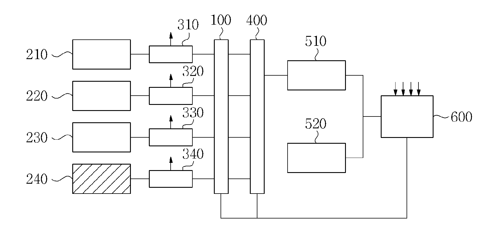
Disclosed herein is an apparatus for controlling a fuel cell heating value. The apparatus includes stack condition sensors which senses conditions of respective fuel cell stacks, and a control unit. Based on conditions of the fuel cell stacks sensed by the stack condition sensors, when at least one conditioning target stack having a heating value that is out of a preset heating value threshold range is sensed, the control unit forms a conditioning target stack group including the sensed at least one conditioning target stack or at least two conditioning target stack groups including the sensed at least one conditioning target stack and connects each of the conditioning target stack groups to at least one of at least two heating value conditioning units.

Description

CROSS REFERENCE TO RELATED APPLICATION[0001]This application claims the benefit of Korean Patent Application No. 10-2013-0165615, filed on Dec. 27, 2013, entitled “DEVICE AND METHOD FOR CONTROLLING FUEL CELL HEATING VALUE”, which is hereby incorporated by reference in its entirety into this application.BACKGROUND OF THE INVENTION[0002]1. Technical Field[0003]The present invention relates generally to fuel cell systems and, more particularly, to an apparatus and method for controlling a heating value of a fuel cell including a plurality of fuel cell stacks.[0004]2. Description of the Related Art[0005]Producing electricity and heat from fuel, fuel cells are configured in such a way that a plurality of fuel cell stacks is connected to each other to increase the capacity. Mechanically connected to each other, and receiving fuel, air and additives for thermochemical reactions, fuel cell stacks or stack modules, each of which includes a plurality of fuel cell stacks, are stacked on top of...

Claims


Application Information

Patent Timeline
IPC IPC(8): H01M8/04
CPCH01M8/04365H01M8/04007H01M8/2465H01M8/04589H01M8/04731H01M8/04559H01M8/04619H01M8/04679H01M8/04701H01M8/0494Y02E60/50H01M8/0432H01M8/2484
Inventor WU, SEONG JEYOO, KYUNG BINKIM, YOUNG DAE
Owner SK INNOVATION CO LTD
Learn More