Arrangement with a vacuum pump and method of compensating magnetic field produced by magnetic interference field of at least one vacuum pump component

a vacuum pump and magnetic interference technology, applied in the direction of bearings, dynamo-electric machines, shafts, etc., can solve the problem of generating magnetic interference and other problems

Active Publication Date: 2017-11-21
PFEIFFER VACUUM GMBH
View PDF22 Cites 0 Cited by
  • Summary
  • Abstract
  • Description
  • Claims
  • Application Information

AI Technical Summary

Benefits of technology

[0019]It can be sufficient to compensate the magnetic interference field only in one plane. However, better results are achieved when the magnetic interference field is compensated completely, i.e., each spatial direction X, Y, Z is associated with at least one compensation coil so that the magnetic interference field can be compensated in three directions, i.e., in all of the three spatial directions X, Y, Z.
[0027]The compensation electronics can derive the rotation—synchronous compensation principal frequency via an induction coil. The amplitude and phase variation of the current in at least one coil permits to minimize the resulting field which, in turn, permits to minimize path deviations and loads, e.g., in an electronic microscope.
[0034]According to a further advantageous embodiment, the at least one compensation coil is arranged in or on the vacuum pump. This insures a compact construction of the inventive arrangement.
[0043]Rotary vane pumps are oil-superimposed rotary displacement pumps. The pump system consists of a housing, an eccentric rotor, slides movable radially by centrifugal and spring forces, inlet, and outlet. An inlet valve is provided as a vacuum safety valve and is always open during operation. Inside the housing, there is a working chamber limited by a stator, a rotor, and the slides. The eccentric rotor and the slides divide the working chamber in two separate chambers with variable volumes. When the rotor rotates, gas flows into the increased compression chamber until it is closed by the second slide. Finally, the enclosed gas is compressed until the outlet valve opens against the atmospheric pressure. The outlet valve is oil-superimposed. When the outlet valve opens, a small amount of oil leaks into the compression chamber and effects lubrication and sealing of the slide against the housing (the stator).
[0058]According to still another embodiment of the invention, the inventive method compensates the magnetic interference field with at least one compensation coil arranged in or on the vacuum pump. Thereby a compact structure of the vacuum pump is achieved.

Problems solved by technology

The magnetic interference can also be generated by the motor that drives the rotor.

Method used


Image

  • Arrangement with a vacuum pump and method of compensating magnetic field produced by magnetic interference field of at least one vacuum pump component
  • Arrangement with a vacuum pump and method of compensating magnetic field produced by magnetic interference field of at least one vacuum pump component
  • Arrangement with a vacuum pump and method of compensating magnetic field produced by magnetic interference field of at least one vacuum pump component

Examples


Embodiment Construction

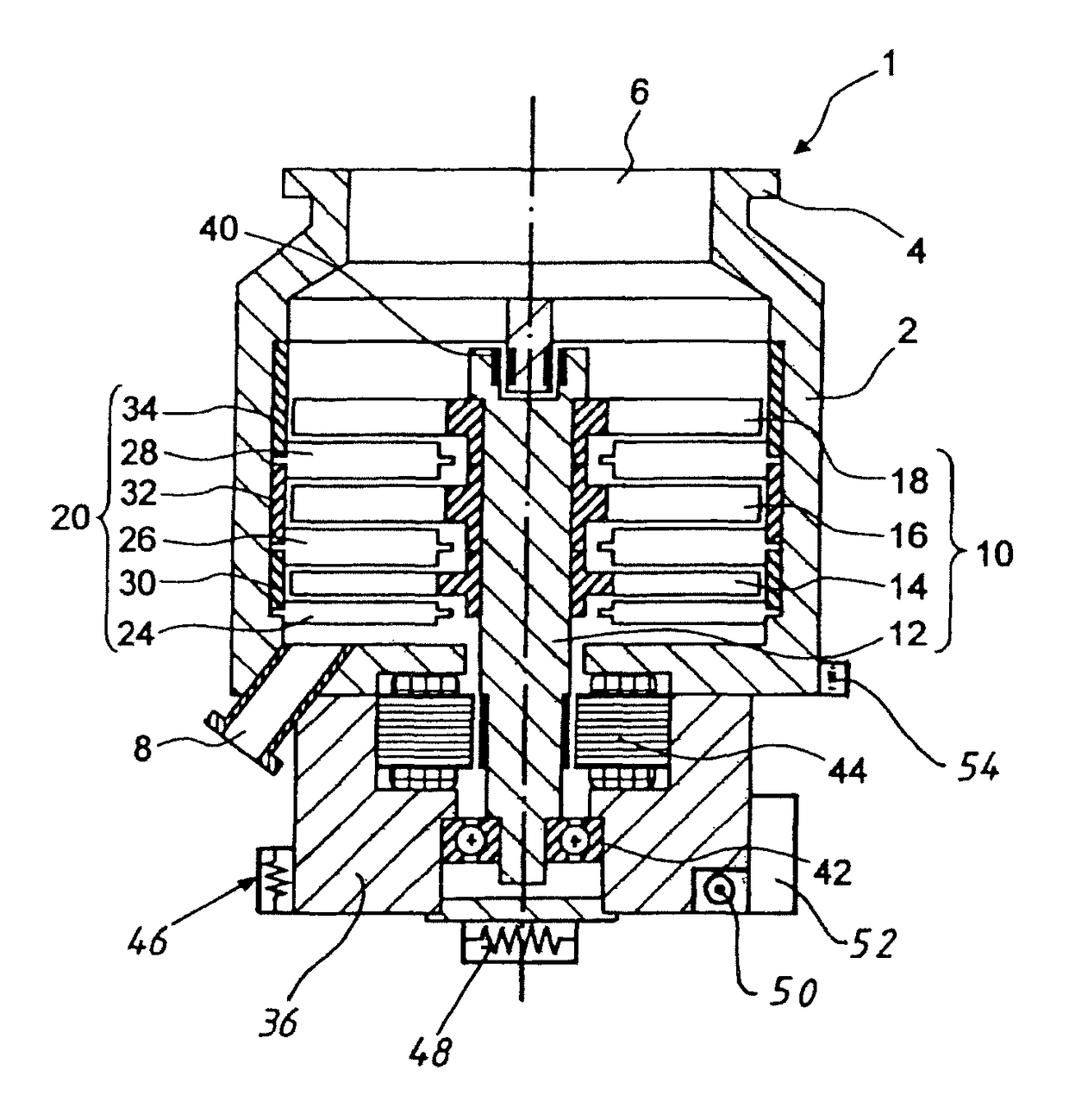
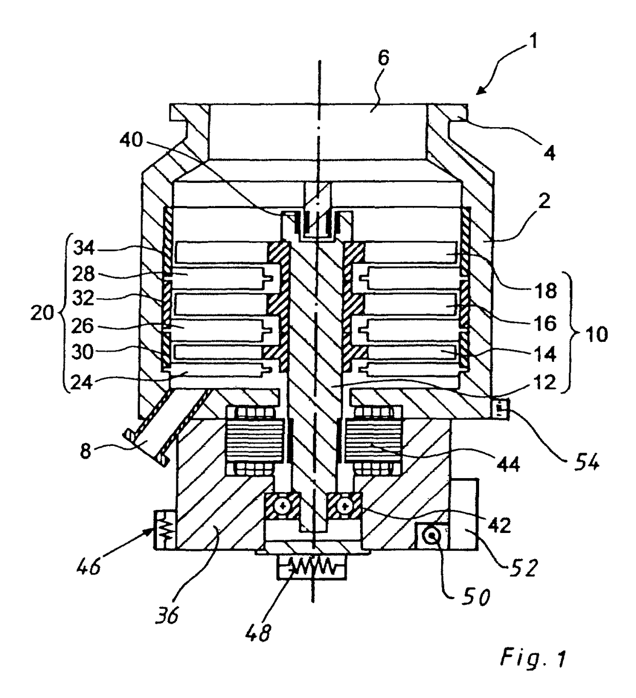
[0064]FIG. 1 shows a cross-sectional view of a turbomolecular pump 1 having a flange 4 releasably securable to a flange of a to-be-discharged chamber (not shown). The gas is aspirated through a suction opening 6 into the pump 1 and is discharged through an outlet 8. A rotor 10 and a stator 20 are located in a housing 2 of the pump. The cooperation of the rotor and stator provides for gas delivery. The rotor 10 includes a shaft 12 on which a forevacuum side rotor disc 14, an intermediate rotor disc 16, and a high vacuum side rotor disc 18 are provided. Each of the rotor discs 14, 16, 18 has several blade assemblies formed of separate blades.

[0065]The shaft 12 is rotatably supported, at its high vacuum side, by a permanent magnetic bearing 40 and at its forevacuum side, by a roller bearing 42. A drive 44 rapidly rotates the rotor with a speed of 10,000 revolutions per minute. The stator has a forevacuum side stator disc 24, an intermediate stator disc 26, and a high vacuum side stator...


PUM


Abstract

An arrangement includes a vacuum pump having a rotor, and a drive unit for driving the rotor and having at least one magnetic interference field-generating component and at least one compensation coil for compensating the magnetic interference field generated by the at least one component.

Description

BACKGROUND OF THE INVENTION[0001]1. Field of the Invention[0002]The present invention relates to an arrangement with a vacuum pump and a method of compensating a magnetic field produced by at least one vacuum pump component, e.g., a magnetic bearing and / or motor.[0003]2. Description of the Prior Art[0004]Since long ago turbomolecular pumps are used in vacuum technology for producing high and ultra-high vacuum. There, the vacuum production is based on a rotor having a plurality of blades offset relative to each other along the rotor axis and between which stator blades are arranged.[0005]Usually, rotors are rotatably supported, in particular, in the turbomolecular pumps by at least one radially arranged magnetic bearing. Often, these magnetic bearings are supported axially by a second bearing, e.g., a ball bearing that insures an axial and radial stabilization.[0006]Such a turbomolecular pump is disclosed, e.g., in DE 10 2010 052 660 A1.[0007]A magnetic bearing usually is formed of s...

Claims


Application Information

Patent Timeline
Patent Type & Authority Patents(United States)
IPC IPC(8): H02K7/09F04D29/66H01J37/32F04D29/54F04B37/08F04B37/14F04D27/02F04D29/64F04D19/04F04D13/06F04D29/05F04D29/058
CPCF04D29/644F04B37/08F04B37/14F04D19/04F04D19/042F04D29/542F04D29/665H01J37/32834F04D27/0292F16C2360/45F04D29/058F04D25/06F04D29/661F16C32/0402F16C32/0425
Inventor CONRAD, ARMIN
Owner PFEIFFER VACUUM GMBH
Why Eureka
Try Eureka