Bare optical fiber coating device and bare optical fiber coating method

a technology of coating device and coating method, which is applied in the direction of glass optical fibre, cladded optical fibre, optical waveguide light guide, etc., can solve the problems of difficult in practice to control the resin flow in the first and second resin paths, the probability of coating quality problems, and the difficulty of preventing the occurrence of problems. to achieve the effect of reducing the thickness deviation of the coating layer and reducing the variation of the thickness deviation

Active Publication Date: 2020-02-18
FUJIKURA LTD
View PDF16 Cites 0 Cited by
  • Summary
  • Abstract
  • Description
  • Claims
  • Application Information

AI Technical Summary

Benefits of technology

[0048]According to the above aspects of the present invention, it is possible to minimize the thickness deviation of the coating layer, variations in thickness deviation in the longitudinal direction of the optical fiber, or variations in the fiber diameter even when the bare optical fiber is inserted into the coating device at high speed, that is, even when the bare optical fiber is coated at a high drawing speed.

Problems solved by technology

Due to the increase in the drawing speed, a coating quality problem is likely to occur when manufacturing the optical fiber by coating the bare optical fiber with a resin.
In practice, however, it has been difficult to prevent the occurrence of the problems, such as thickness deviation, at the high drawing speed using the conventional techniques.
That is, in the techniques disclosed in PTLs 1 and 2, it has been difficult in practice to control the resin flow in the first and second resin paths in many cases.
However, there is a high possibility that the resin will not be returned to the resin reservoir uniformly due to a relationship, such as a pressure difference.
In addition, a resin flow difference (difference in the flow rate or the amount of flow) in the circumferential direction in a merging portion of the resin flows in the first and second resin paths and the circulation flows generated in the intermediate die hole and the coating die hole may disturb the circulation flow in the die hole.
Due to these influences, especially at the time of high drawing speed, the circulation flow of the resin in the coating die hole that is the most important consideration at the time of resin coating is disturbed and the resin flow becomes unstable and uneven, and accordingly, the resin coating thickness becomes uneven.
As a result, problems, such as thickness deviation, variations in thickness deviation in the longitudinal direction of the optical fiber, or non-uniform coating diameter, were likely to occur.

Method used


Image

  • Bare optical fiber coating device and bare optical fiber coating method
  • Bare optical fiber coating device and bare optical fiber coating method
  • Bare optical fiber coating device and bare optical fiber coating method

Examples


example 1

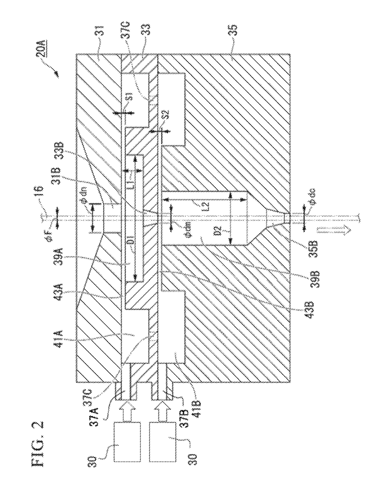
[0130]Example 1 is an example to examine the influence of the length L1 of the first resin circulation chamber 39A and the length L2 of the second resin circulation chamber 39B.

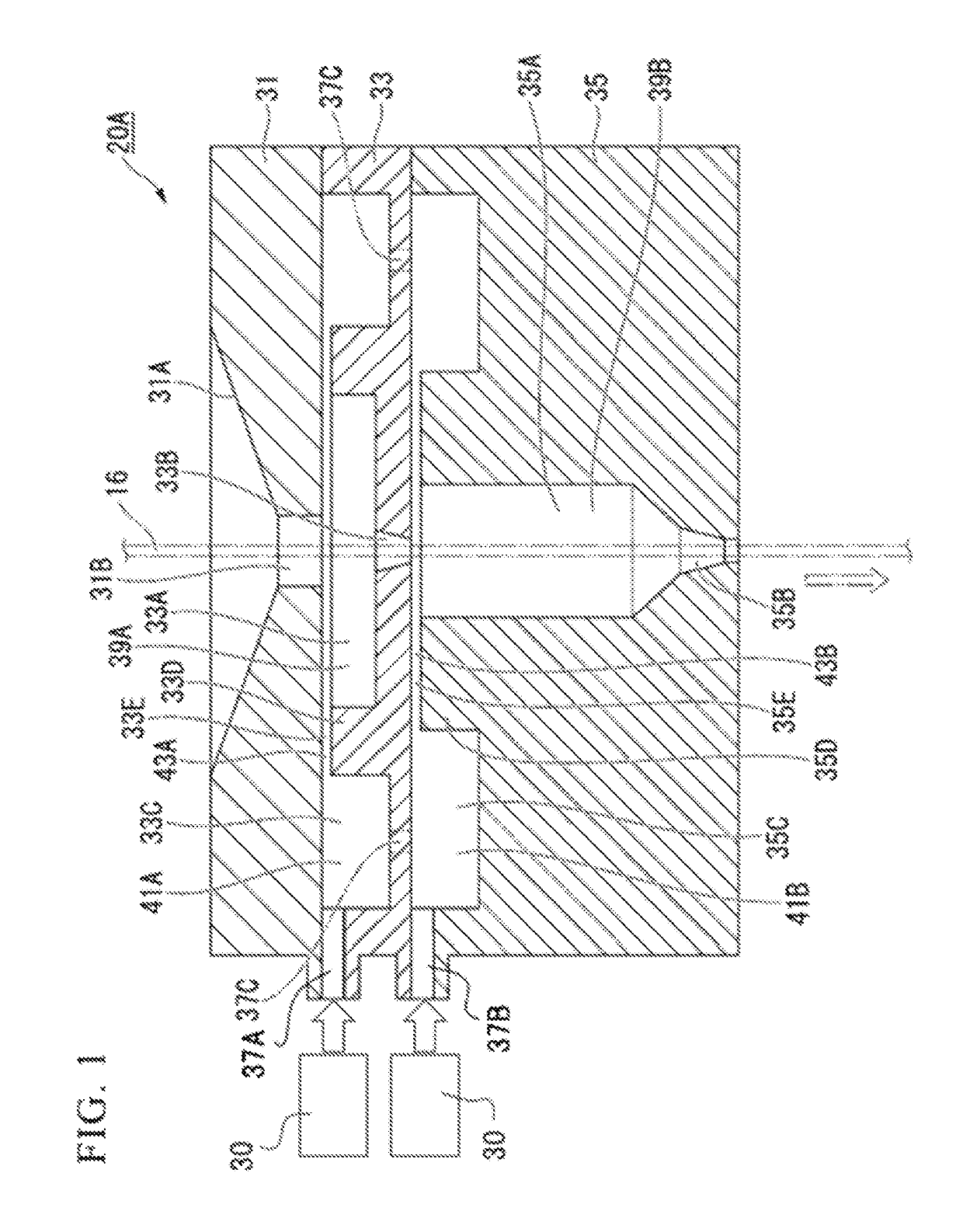
[0131]When manufacturing the optical fiber 24 using the optical fiber manufacturing apparatus shown in FIG. 23, the device shown in FIG. 1 was used as the coating devices 20A and 20B. For resin coating, as shown in FIG. 23, an independent coating method for two-layer coating was applied in which coating and curing were performed at two places using the two resin coating devices 20A and 20B and the two UV curing devices 22A and 22B. That is, the optical fiber preform 12 was heated and melted in the heating furnace and the bare optical fiber 16 of ϕ125 μm was pulled out, and then the bare optical fiber was cooled to the appropriate temperature by the cooling device 18. Then, first-stage coating (primary coating) was performed by coating the bare optical fiber with an ultraviolet curable resin using the first-st...

example 2

[0141]Example 2 is an example to examine the influence of the inner diameter D1 of the first resin circulation chamber 39A and the inner diameter D2 of the second resin circulation chamber 39B.

[0142]From Example 1 described above, the optimal ranges of the lengths L1 and L2 of the respective circulation chambers were obtained. Therefore, in Example 2, the inner diameters D1 and D2 of the first and second resin circulation chambers 39A and 39B were changed independently in order to check the optimal ranges. That is, the inner diameter D1 of the first resin circulation chamber 39A was changed to be within a range of 2 mm to 10 mm in a state in which the inner diameter D2 of the second resin circulation chamber 39B was fixed to ϕ3 mm. The inner diameter D2 of the second resin circulation chamber 39B was changed to be within a range of 1 mm to 10 mm in a state in which the inner diameter D1 of the first resin circulation chamber 39A was fixed to ϕ5 mm. Other drawing conditions and evalu...

example 3

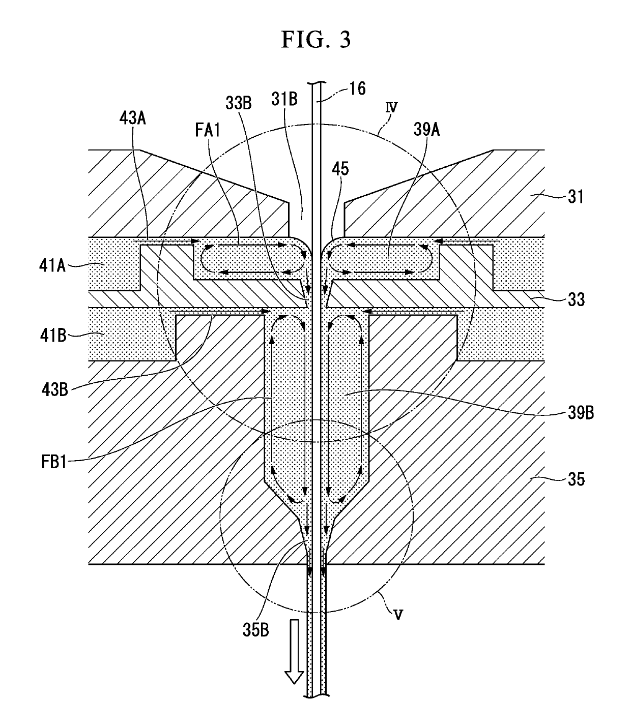
[0147]Example 3 is an example used to examine the influence of the internal pressure of the first and second resin circulation chambers 39A and 39B.

[0148]That is, in the optimal size of each circulation chamber determined in Examples 1 and 2 described above, the amount of eccentricity and the variation when changing the difference between the resin pressure applied to the first circulation chamber and the resin pressure applied to the second circulation chamber were examined.

[0149]Here, a system was used that supplied a resin toward the first and second resin circulation chambers 39A and 39B in the resin coating device from the same resin supply source 30 and supplied the resin to each of the resin circulation chambers 39A and 39B through branching in the resin coating device. Resin supply pressure to the first resin circulation chamber 39A and resin supply pressure to the second resin circulation chamber 39B were adjusted by causing a pressure loss intentionally by adjusting the fl...


PUM

PropertyMeasurementUnit
lengthaaaaaaaaaa
lengthaaaaaaaaaa
lengthaaaaaaaaaa

Abstract

A bare optical fiber coating device includes: a nipple having a nipple hole through which a bare optical fiber is inserted vertically from above; an intermediate die that has an intermediate die hole through which the bare optical fiber passing through the nipple hole is inserted and that is disposed vertically below the nipple; a first coating die that has a first coating die hole through which the bare optical fiber passing through the intermediate die hole is inserted and that is provided vertically below the intermediate die; and a first resin circulation chamber that is formed by the nipple and the intermediate die, is formed between the nipple hole and the intermediate die hole in an annular shape surrounding the bare optical fiber passing through the nipple hole, and is configured to circulate liquid resin.

Description

CROSS REFERENCE TO RELATED APPLICATIONS[0001]This application is a continuation application based on a PCT Patent Application No. PCT / JP2014 / 065008, filed Jun. 5, 2014, whose priority is claimed on Japanese Patent Application No. 2013-121051, filed on Jun. 7, 2013.BACKGROUND OF THE INVENTION[0002]Field of the Invention[0003]The present invention relates to a coating device for manufacturing an optical fiber by applying a resin as a protective coating layer on a bare optical fiber and a method of manufacturing an optical fiber using the coating device, and in particular, to a coating device suitable for applying a resin on the bare optical fiber at a high drawing speed (for example, 2000 m / min or more) and a bare optical fiber coating method using the same.[0004]Description of the Related Art[0005]As is well known, in the manufacture of the optical fiber, resin is applied as a protective coating layer on the surface of the bare optical fiber drawn from the optical fiber preform. In t...

Claims


Application Information

Patent Timeline
Patent Type & Authority Patents(United States)
IPC IPC(8): C03C25/10B29C48/18C03C25/12C03C25/1065B29C48/154B05C3/12B05D5/06G02B6/02
CPCB05D5/06C03C25/12C03C25/10C03C25/1065B05C3/125G02B6/02395B29C48/18B29C48/154
Inventor OKADA, KENJI
Owner FUJIKURA LTD
Why Eureka
Try Eureka