Method and apparatus for network virtualization

a network virtualization and multi-domain technology, applied in the field of network virtualization, can solve the problems of restricting the size of the network, not easy to meet the requirements of network virtualization methods, etc., and achieve the effect of large-scale network virtualization domain and significant reduction of the number of tunnels needed in the network virtualization domain

Active Publication Date: 2015-07-02
ELECTRONICS & TELECOMM RES INST
View PDF6 Cites 9 Cited by
  • Summary
  • Abstract
  • Description
  • Claims
  • Application Information

AI Technical Summary

Benefits of technology

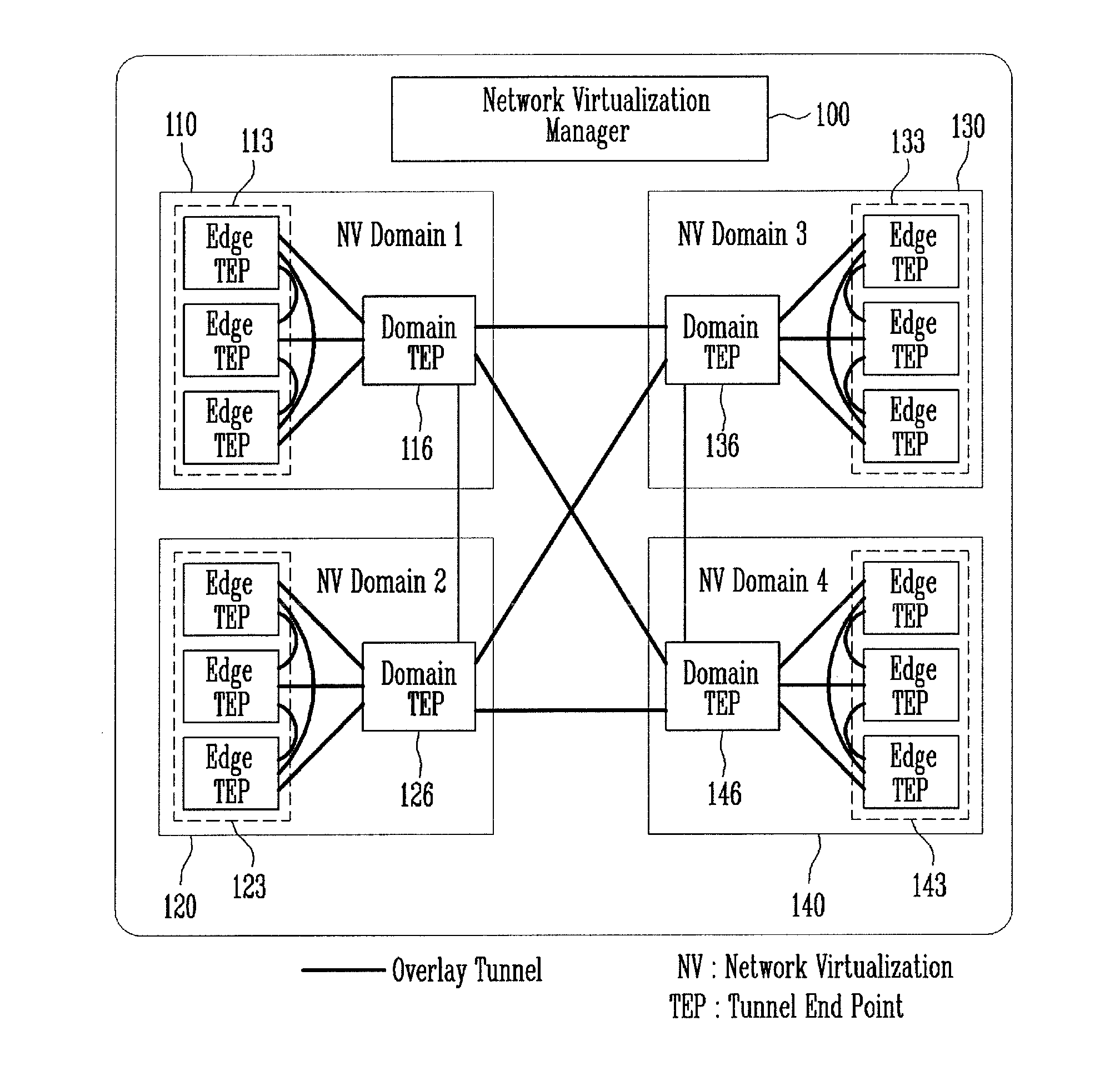
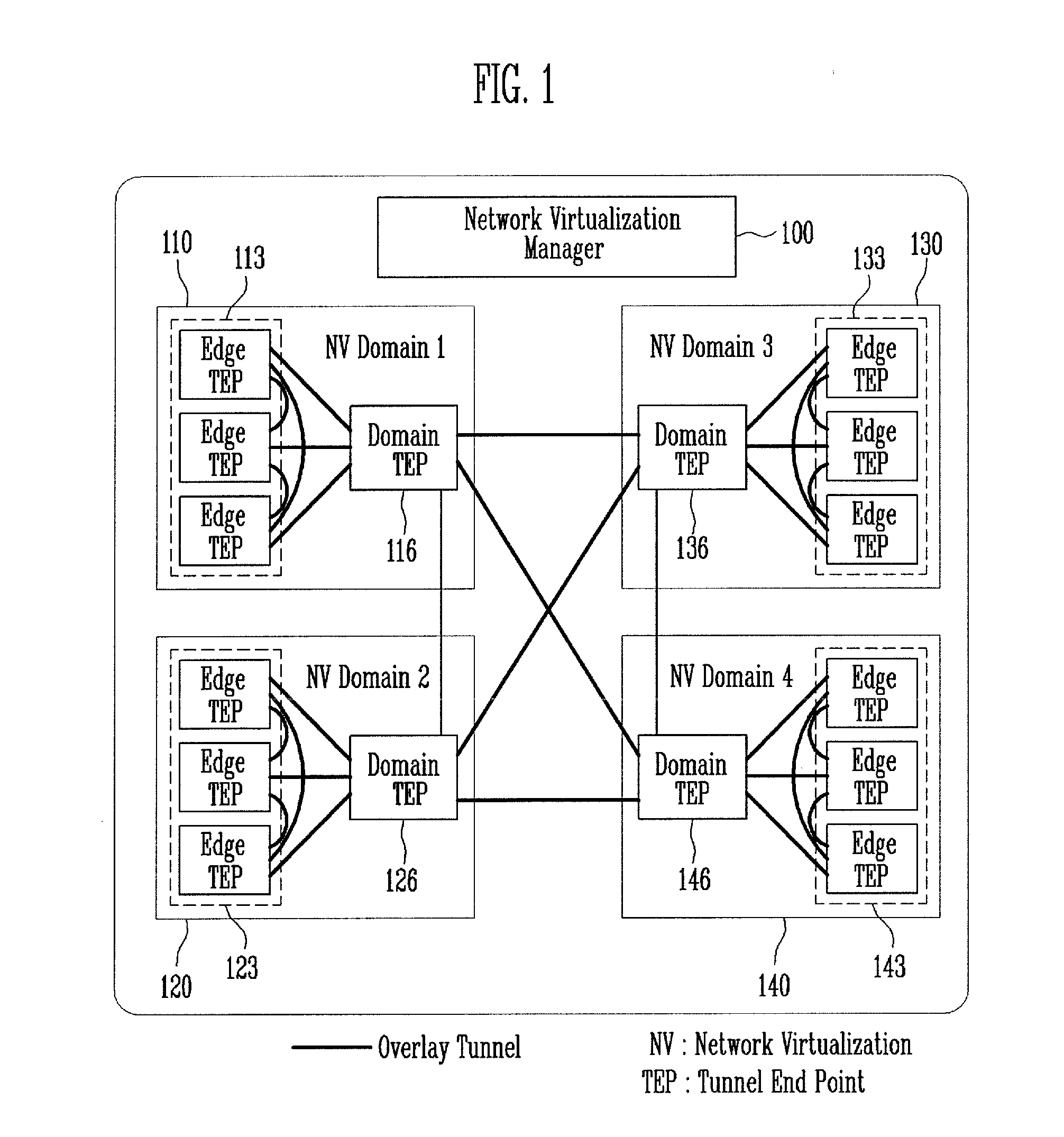
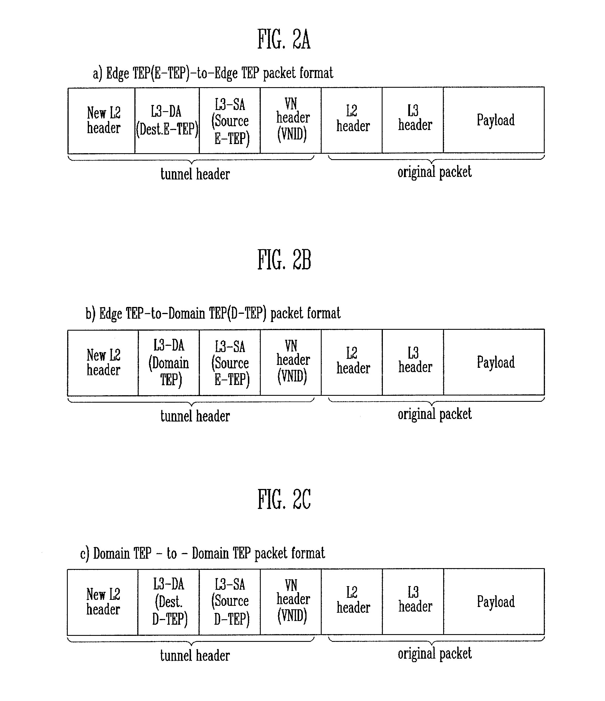
[0012]As aforementioned, by using a method and apparatus for multi-domain network virtualization according to embodiments of the present invention, it is possible to provide expandability in an overlay-based virtual network configured by an L3 tunnel. According to an embodiment of the present invention, by creating a plurality of network virtualization domains of an appropriate size that may be created in a full-mesh tunnel manner, and then having a domain tunnel end point in every domain, and then simply adding a full-mesh connection between domain tunnel end points, it is possible to create one large scale network virtualization domain where a plurality of domains are integrated. In this way, the number of tunnels necessary in a network virtualization domain may be significantly reduced, and thus a large scale network virtualization domain may be constructed.

Problems solved by technology

This restricts expandability, thereby causing a problem of restricting the size of the network (number of network nodes) where a VXLAN or NVGRE may be applied.
Specifically, the greater the N, the more complex the setting becomes, and due to the restriction on the number of tunnels that may be set in TEPs and the restriction on the number of tunnels that may be managed by one network virtualization manager, a network virtualization domain must be restricted to a certain size.
There is need for a virtual network existing over a plurality of IDCs located far from one another geographically, but it is not easy to provide these requirements with conventional network virtualization methods since they lack expandability.

Method used


Image

  • Method and apparatus for network virtualization
  • Method and apparatus for network virtualization
  • Method and apparatus for network virtualization

Examples


Embodiment Construction

[0020]Hereinafter, embodiments will be described in greater detail with reference to the accompanying drawings. Embodiments are described herein with reference to cross-sectional illustrations that are schematic illustrations of embodiments (and intermediate structures). As such, variations from the shapes of the illustrations as a result, for example, of manufacturing techniques and / or tolerances, are to be expected. Thus, embodiments should not be construed as limited to the particular shapes of regions illustrated herein but may include deviations in shapes that result, for example, from manufacturing. In the drawings, lengths and sizes of layers and regions may be exaggerated for clarity. Like reference numerals in the drawings denote like elements.

[0021]Terms such as ‘first’ and ‘second’ may be used to describe various components, but they should not limit the various components. Those terms are only used for the purpose of differentiating a component from other components. For...


PUM


Abstract

Provided herein a network virtualization apparatus and method, the apparatus including a tunnel manager configured to collect tunnel end points information within a network, and to connect each tunnel end point with a tunnel based on the tunnel end point information collected; a tunnel packet end point configured to receive a tunnel packet and process the packet such that an L2 switching may be performed, and to transmit the packet to a domain VSI (virtual switching instance); the domain VSI configured to perform the L2 switching on the processed packet, and to transmit the packet to a tunnel packet generator; and the tunnel packet generator configured to add a tunnel header to the packet for which the L2 switching has been performed to generate a new tunnel packet, and to transmit the new tunnel packet.

Description

CROSS-REFERENCE TO RELATED APPLICATION[0001]The present application claims priority to Korean patent application numbers 10-2013-0165299, filed on Dec. 27, 2013 and 10-2014-0136067, filed on Oct. 8, 2014, the entire disclosure of which is incorporated herein in its entirety by reference.BACKGROUND[0002]1. Field of Invention[0003]Various embodiments of the present invention relate to a network, and more particularly, to a method and apparatus for multi-domain network virtualization.[0004]2. Description of Related Art[0005]Recent trends of IT (information technology) include server virtualization, VM (virtual machine)-based computing, concentration of IT resources on data center, and network virtualization. Network virtualization is a technology where a plurality of virtual networks may be created on a physical network when necessary and can be deleted. This technology may be utilized to configure a network between virtual machines. A generally used overlay-based virtual network is a ...

Claims


Application Information

Patent Timeline
Patent Type & Authority Applications(United States)
IPC IPC(8): H04L12/46H04L12/24H04L12/713H04L12/741H04L29/12H04L45/586H04L45/74
CPCH04L12/4633H04L45/74H04L61/106H04L45/586H04L41/12H04L61/2069H04L45/66
Inventor BYUN, SUNG HYUK
Owner ELECTRONICS & TELECOMM RES INST
Why Eureka
Try Eureka