Rectifier diode fault detection in brushless exciters

a rectifier diode and brushless technology, applied in the field of rectifier diode fault detection, can solve the problems of relatively simple and inexpensive circuit used to execute the method, and achieve the effect of quickly and accurately detection

Active Publication Date: 2015-07-16
ROLLS ROYCE PLC
View PDF4 Cites 24 Cited by
  • Summary
  • Abstract
  • Description
  • Claims
  • Application Information

AI Technical Summary

Benefits of technology

[0026]According to the present invention, a fault in one or more diodes of the rectifier circuit can be detected quickly and accurately. This is particularly advantageous when the method is employed to detect faults in the rotating diode rectifiers on the rotor of a BLSG, for example.
[0027]Furthermore, because the method can be employed with only a single sensor, or detector, arranged to measure e.g. the voltage across the load, the circuit used to execute the method is relatively uncomplicated and inexpensive.

Problems solved by technology

Furthermore, because the method can be employed with only a single sensor, or detector, arranged to measure e.g. the voltage across the load, the circuit used to execute the method is relatively uncomplicated and inexpensive.

Method used


Image

  • Rectifier diode fault detection in brushless exciters
  • Rectifier diode fault detection in brushless exciters
  • Rectifier diode fault detection in brushless exciters

Examples


Embodiment Construction

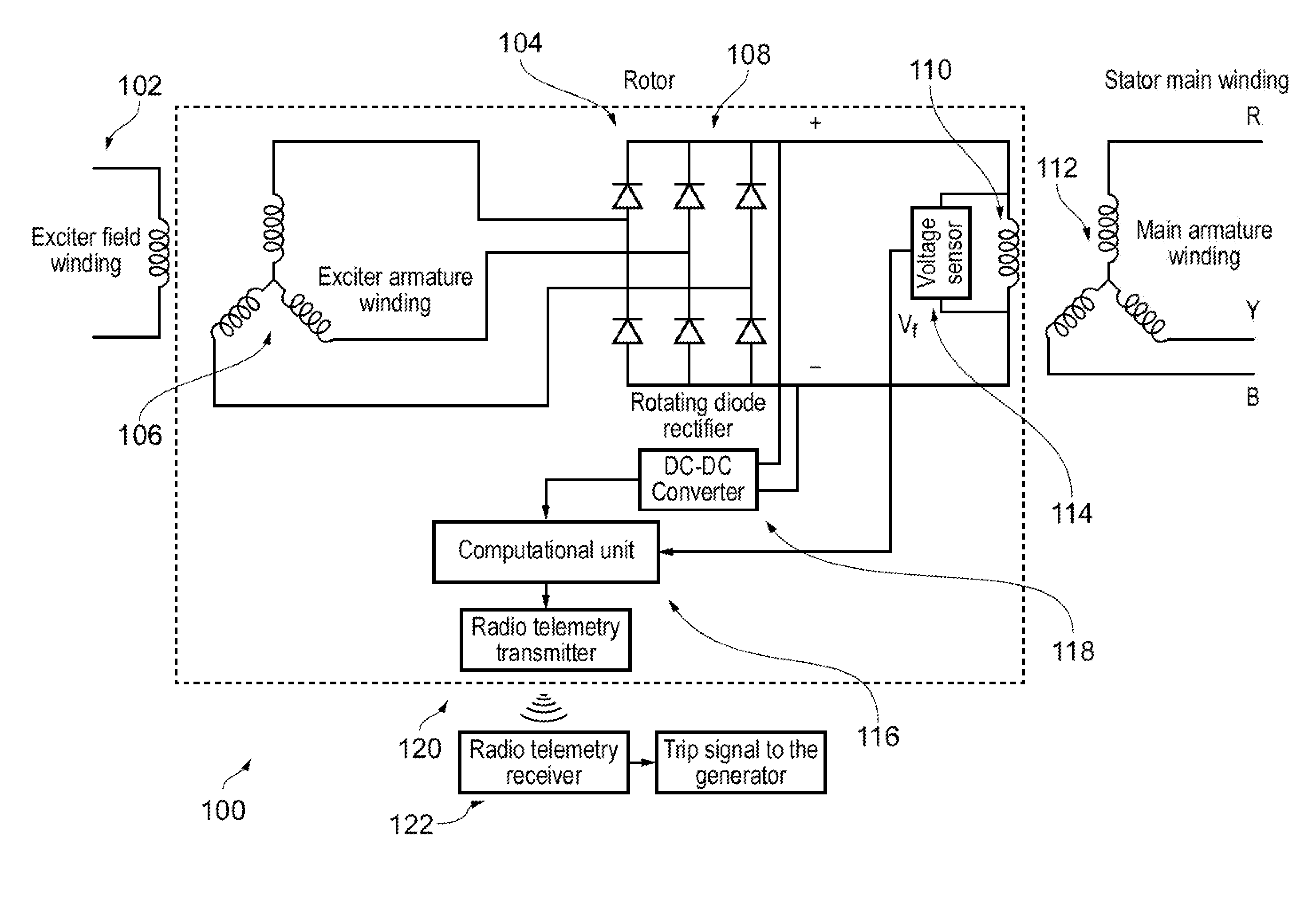
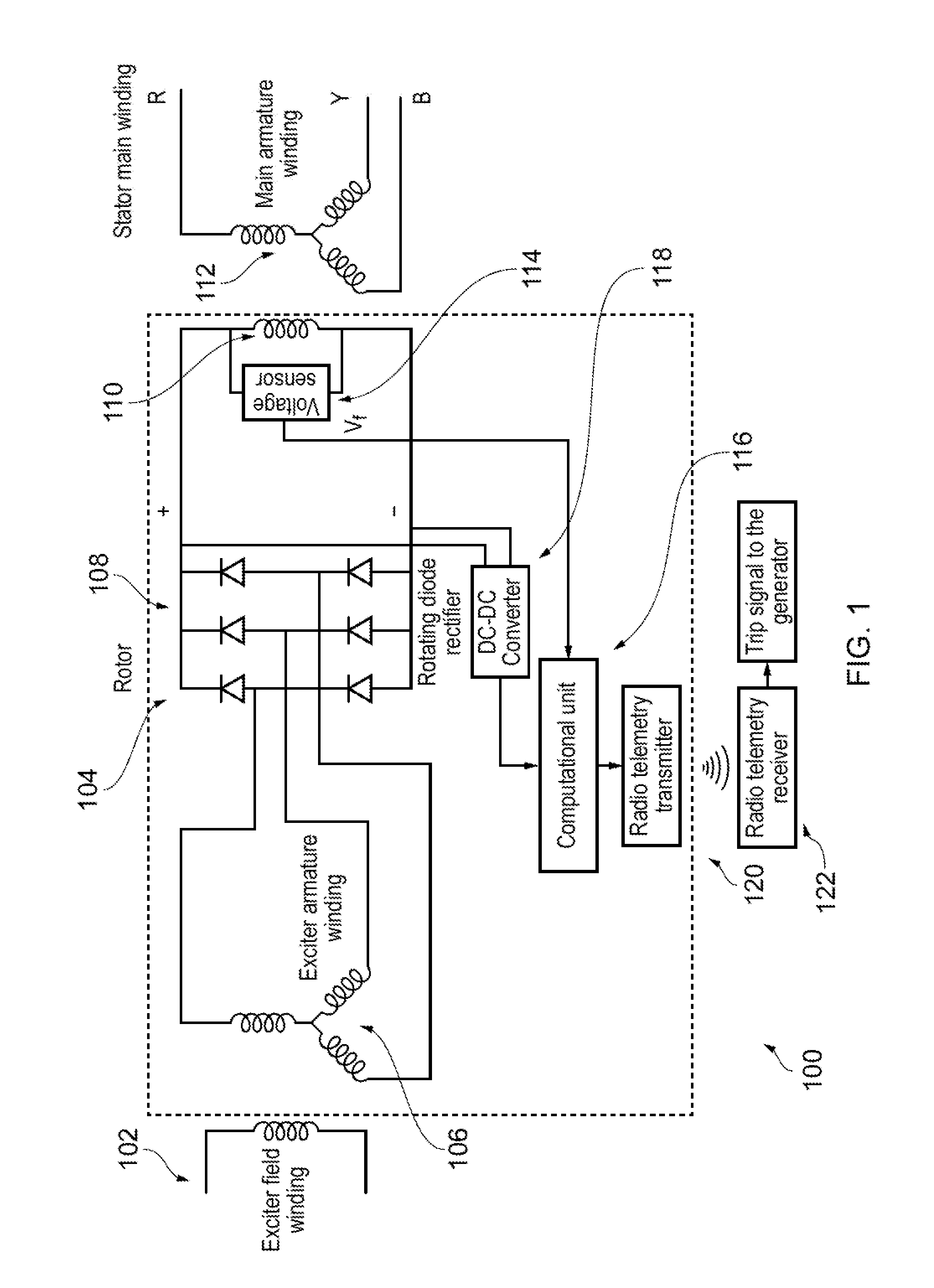
[0066]Fundamentally, in a synchronous generator a DC current is provided for a field winding (or coil) mounted on a rotor, so as to produce a rotor magnetic field. The rotor is then rotated about its axis, e.g. by external means. Thus, sometimes the rotor magnetic field is referred to as a rotating magnetic field. A stator is provided with a stator winding (or coil). As the rotor is rotated the rotating magnetic field induces a voltage (an electromotive force) in the stator winding. Typically the stator winding has a plurality of armatures, whereby the rotating magnetic field induces respectively different voltages in each arm at different parts of the cycle. Thus, the multi-armature stator winding will generate a multi-phase (or polyphase) output in accordance with the number of armatures and the spatial relationship between each armature and the rotating magnetic field.

[0067]The DC current can be provided to the rotor field winding by means of brushes and slip rings. However, in a...


PUM


Abstract

A method of detecting a diode fault in an AC signal rectifier circuit,
    • the AC signal rectifier circuit including a plurality of diodes, and being arranged to supply a rectified output voltage to a load, wherein the method includes the steps of
    • deriving an operating value indicative of the ratio of the voltage magnitudes of a first harmonic frequency and another harmonic frequency of the rectified output voltage across the load; and
    • determining whether a fault has occurred in one or more diodes on the basis of the derived operating value.
The first harmonic frequency is preferably the fundamental harmonic frequency, and/or the another harmonic frequency is preferably the 6th harmonic frequency.

Description

FIELD OF THE INVENTION[0001]The present invention relates to the detection of rectifier diode faults, for example in exciter circuits, in brushless generators such as brushless synchronous generators.BACKGROUND OF THE INVENTION[0002]The brushless synchronous generator (BLSG) is widely used in aircraft and marine vessels for onboard power generation and it is also used as a shaft generator in energy efficient hybrid propulsion systems for marine vessels. The brushless excitation offers increased reliability and reduced maintenance requirements for the generator.[0003]The exciter is a key component of a generator and the generator's output voltage is regulated by controlling the exciter's field current. The main function of the excitation system is to provide variable DC current to excite the main magnetic field in the rotor. Furthermore, it supports short time overload capability, controlling the terminal voltage with suitable accuracy, ensures stable operation and keep machine withi...

Claims


Application Information

Patent Timeline
Patent Type & Authority Applications(United States)
IPC IPC(8): G01R31/26G01R23/02
CPCG01R23/02G01R31/2632G01R31/343G01R31/40H02H7/1255H02K11/20
Inventor VISWANATHAN, VAIYAPURIGUPTA, AMIT KUMARGAJANAYAKE, CHANDANA JAYAMPATHINADARAJAN, SIVAKUMAR
Owner ROLLS ROYCE PLC
Why Eureka
Try Eureka