
System and Method for Optimal Power Flow Analysis

a power flow and optimal technology, applied in the field of optimizing power flows, can solve the problems of inefficient linear under-approval of the cost function representing the power flow, and the inability of the widely used implementation of the sdp using interior point methods to accept the input specified by the previous search, so as to accelerate the convergence of methods and increase the computational efficiency of the opf problem

Active Publication Date: 2015-07-16
MITSUBISHI ELECTRIC RES LAB INC
View PDF0 Cites 24 Cited by
  • Summary
  • Abstract
  • Description
  • Claims
  • Application Information

AI Technical Summary

Benefits of technology

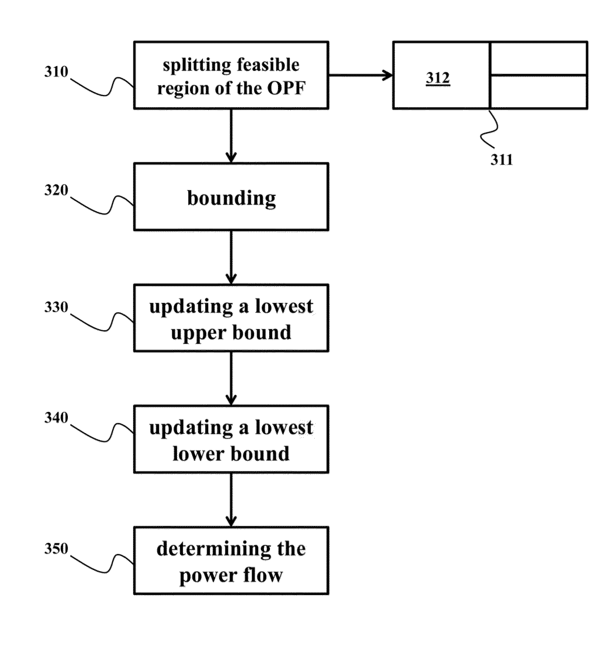
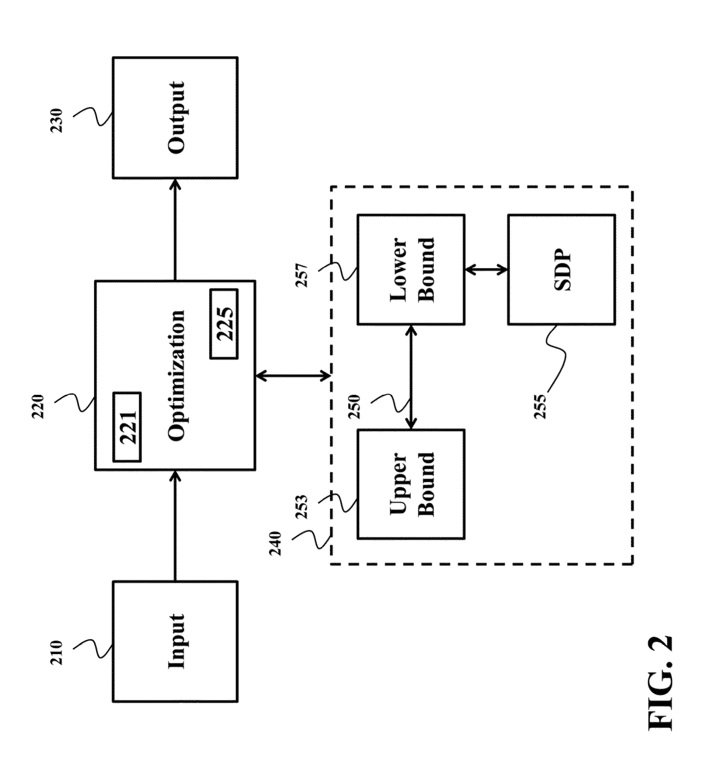
[0006]In addition, some embodiments are based on a realization that SDP relaxation of the OPF or portions of the OPF should be used for determining the lower bounds on the optimal objective function. Usually, the branch and bound methods are implemented using linear under-approximation of the optimized function, because such approximation can be efficiently performed. However, the embodiments recognized that in the context of the power flow analysis of the power grid, the linear under-approximation of the cost function representing the power flow is inefficient due to the shallow structure of the cost function. Hence, it was realized that despite of complexity of the SDP over the linear under-approximation, the usage of the SDP approximation in the context of the power grids is advantageous.
[0007]Some embodiments of the invention are based on an additional realization that the branch and bound method should be implemented such that a search for the lowest lower and upper bound in a nested region can use, as a starting point, the result of the search in the region from which the nested region was partitioned according to the branch and bound principles. This realization is based in part on the recognition that the structure of the power grid has patterns or similarities repeated over the span of the grid. Thus, the result of the search in one region can be used to speed up the search over a different region.
[0009]Another embodiment uses alternating direction method of multipliers (ADMM) method. Specifically, the usage of the ADMM method for SDP relaxation in a current iteration of the branch and bound method allows reusing the outputs of the previous iteration of the branch and bound method to accelerate the convergence of the method.
[0010]The resulting modifications of the branch and bound method allows to significantly increase the computational efficiency of the OPF problem. For example, some embodiments of the invention solve the OPF problems that cannot be solved using conventional approaches due to lack of memory to fit within a single processor. This efficiency allows using the embodiments to solve multi-period optimal power flow (MOPF) problems to global optimality. The multi-period version of the OPF is time coupled due to the integration of storage systems into the power grid, and ramp constraints on the generators.

Problems solved by technology

However, the embodiments recognized that in the context of the power flow analysis of the power grid, the linear under-approximation of the cost function representing the power flow is inefficient due to the shallow structure of the cost function.
Unfortunately, the widely used implementation of the SDP using interior point methods cannot accept the input specified by the previous search.

Method used


Image

  • System and Method for Optimal Power Flow Analysis
  • System and Method for Optimal Power Flow Analysis
  • System and Method for Optimal Power Flow Analysis

Examples


Embodiment Construction

[0039]Electrical Power Network Topology and Representative Graph

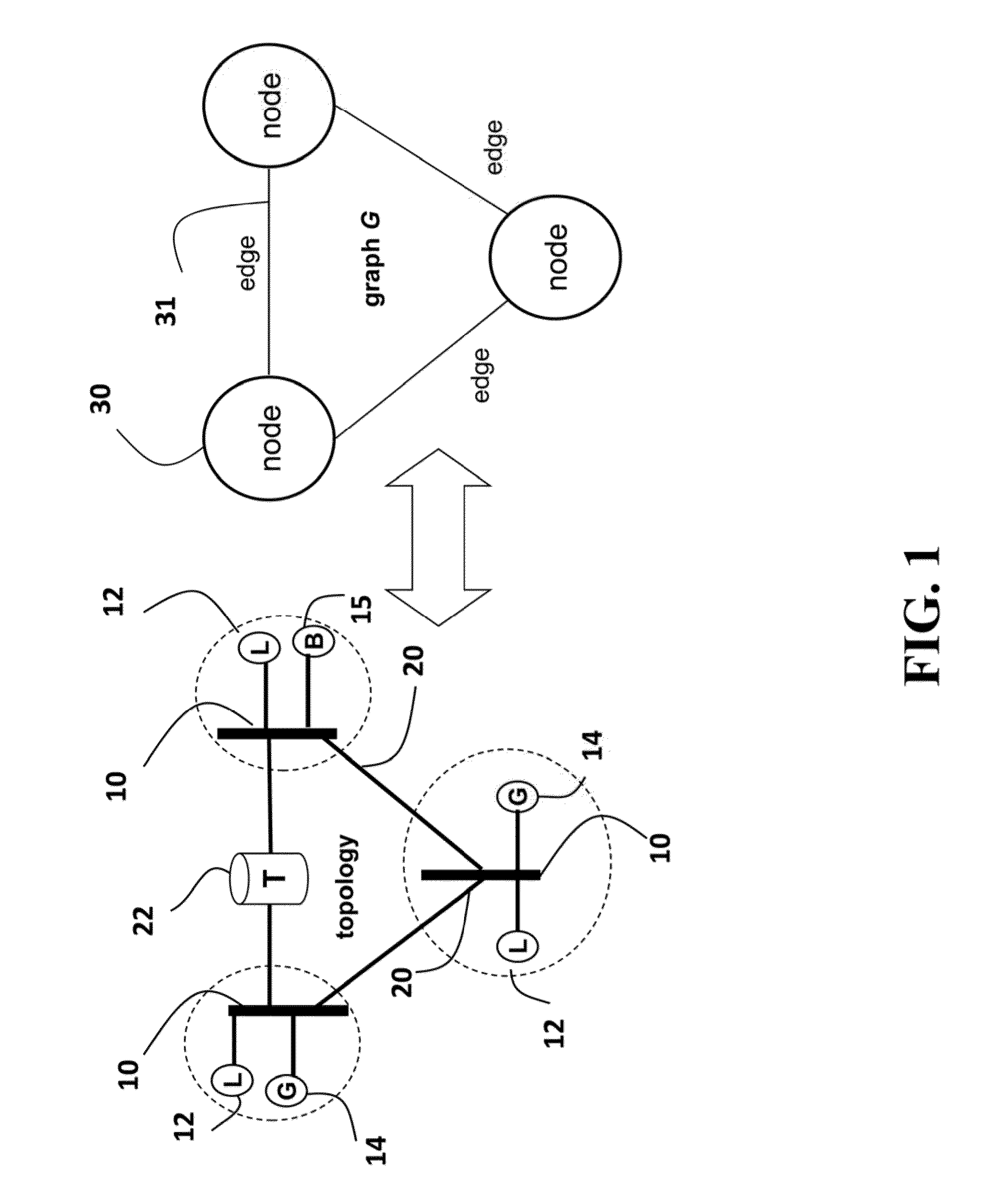
[0040]FIG. 1 shows a topology of an electric power grid that can use embodiments of the invention. The network can include AC components, and DC components connected by convertors. The variables and constraints that control the operation of the power grid are continuously controllable.

[0041]The power grid includes buses 10 locally connected to loads (L) 12 and generators (G) 14. The buses are interconnected by transmission lines 20, also known as branches (B). Some of the transmission lines can be connected to transformers (T) 22. The topology and / or structure of the power grid can be represented by a graph G of nodes 30 representing, e.g., generators and connected loads). The nodes in the graph are connected by edges 31 representing transmission lines.

[0042]The generators supply active power (measured in, e.g., Mega Watts (MW)), and reactive power (measured in Mega Volt Ampere Reactive (MVar)). The loads consume the po...


PUM


Abstract

A method determines a power flow of a power grid by optimizing an objective function representing an operation of the power grid using a spatial branch and bound (BB) framework for determining iteratively upper and lower bounds of the objective function. During the optimization, the lower bounds are determined using a semi-definite programming (SDP) relaxation of an optimal power flow (OPF) problem.

Description

FIELD OF THE INVENTION[0001]The present invention relates generally to power grids, and more particularly to optimizing power flows in the power grids.BACKGROUND OF THE INVENTION[0002]The Optimal Power Flow (OPF) problem for a power grid having alternating current (AC) circuits concerns the problem of determining bus voltages and generator power levels to minimize a cost function representing an operation of the power grid. The cost functions can include generator cost, resistive losses or tertiary voltage control. The minimization of the cost function is subject to OPF constrains that can include the AC power flow constraints, bounds on power generation, bounds on bus voltage magnitudes, bounds on thermal losses, and limits on power transfer on lines.[0003]The conventional methods relax the OPF to find a solution using, e.g., the second order cone programming (SOCP). See, e.g., U.S. 2012 / 0150504. However, such approach provides optimal solution only under satisfaction of sufficient...

Claims


Application Information

Patent Timeline
Patent Type & Authority Applications(United States)
IPC IPC(8): G06N5/04G06Q50/06
CPCG06Q50/06G06N5/04G06F17/11H02J2203/20Y02E40/70Y02E60/00Y04S10/50Y04S40/20H02J3/06
Inventor RAGHUNATHAN, ARVIND U.NIKOVSKI, DANIEL NIKOLAEVGOPALAKRISHNAN, AJIT
Owner MITSUBISHI ELECTRIC RES LAB INC
Learn More