Liquid ejecting head unit and liquid ejecting apparatus
- Summary
- Abstract
- Description
- Claims
- Application Information
AI Technical Summary
Benefits of technology
Problems solved by technology
Method used
Image
Examples
embodiment 1
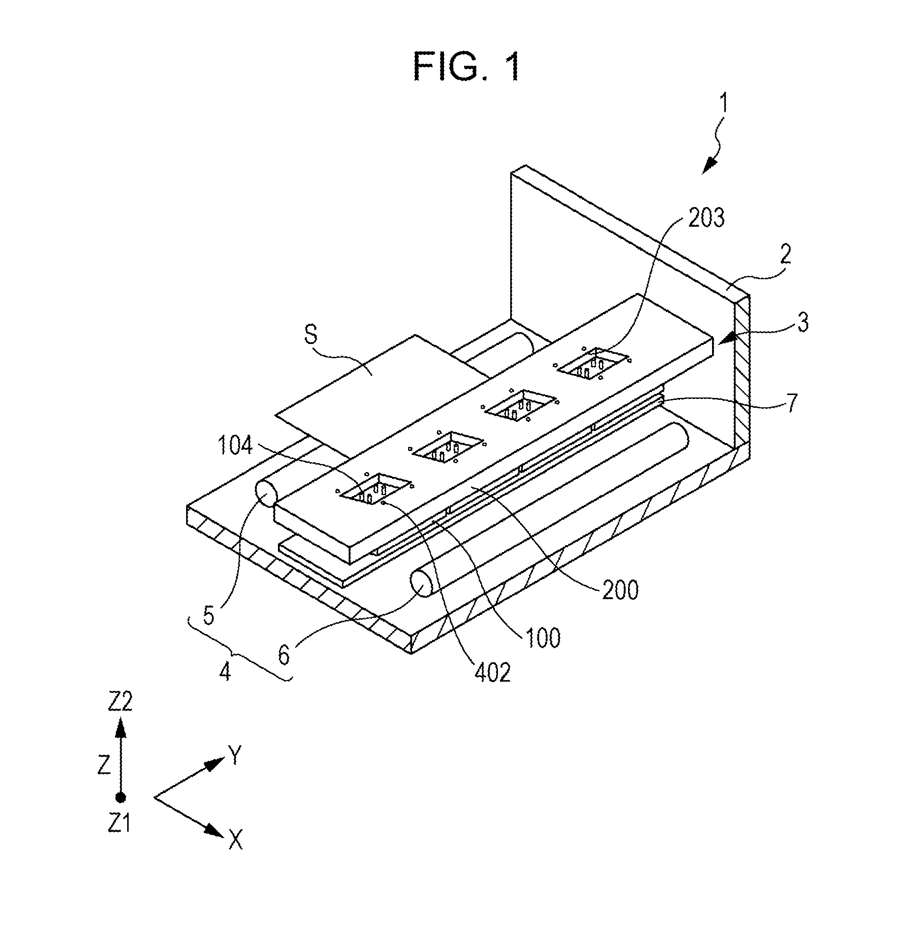
[0034]FIG. 1 is a perspective view showing a schematic configuration of an ink jet type recording apparatus which is an example of a liquid ejecting apparatus according to Embodiment 1 of the invention.
[0035]An ink jet type recording apparatus which is an example of a liquid ejecting apparatus according to this embodiment is a so-called line type recording apparatus which performs printing by transporting a recording sheet S such as paper which is a recording medium, while an ink jet type recording head unit which is an example of a liquid ejecting head unit is fixed.
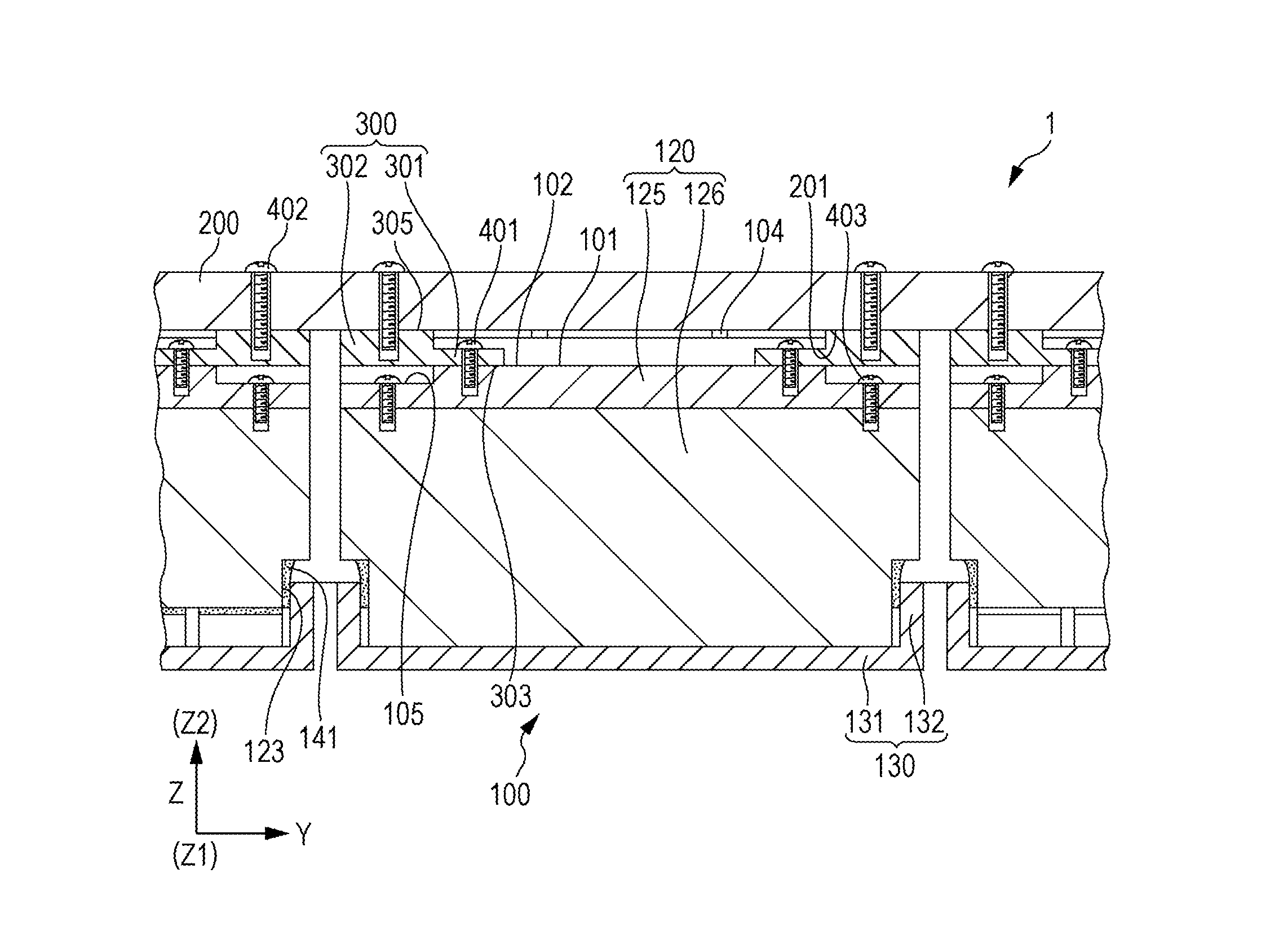
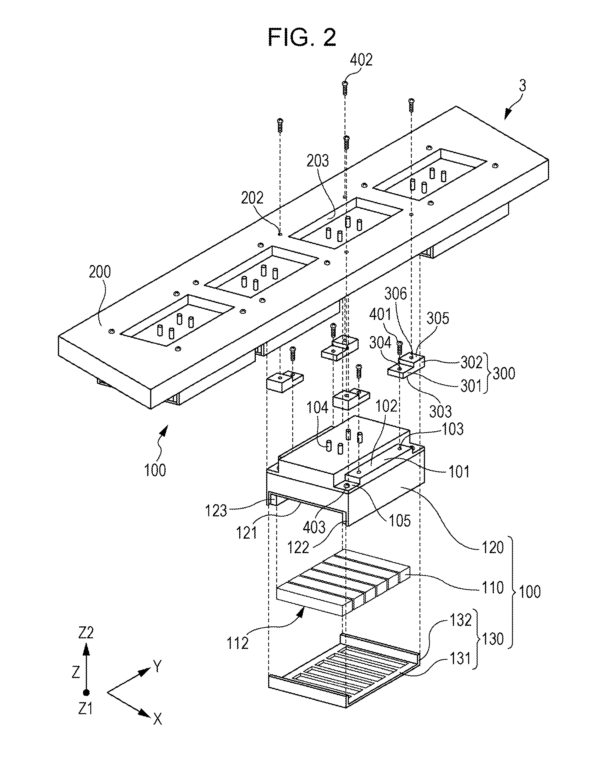
[0036]Specifically, as shown in FIG. 1, an ink jet type recording apparatus 1 is provided with an apparatus main body 2, an ink jet type recording head unit 3 (hereinafter also referred to simply as a head unit 3) provided with a plurality of ink jet type recording heads 100 and fixed to the apparatus main body 2, transport means 4 which transports the recording sheet S, and a supporting member 7 which supports the reco...
embodiment 2
[0105]FIG. 7 is a cross-sectional view of a main section of an ink jet type recording head unit which is an example of a liquid ejecting head unit according to Embodiment 2 of the invention. In addition, the same member as that in Embodiment 1 described above is denoted by the same reference numeral and overlapping description is omitted.
[0106]As shown in FIG. 7, the head unit 3 according to this embodiment is provided with an ink jet type recording head 100A, the head fixing substrate 200, and the spacer 300.
[0107]In the ink jet type recording head 100A, a flange portion 106 provided to protrude further in the second direction Y than the liquid ejecting surface 112 side is provided on the Z2 side which is the side opposite to the liquid ejecting surface 112 in the third direction Z.
[0108]The flange portion 106 is disposed at a height which does not interfere with the first transport roller 5 and the second transport roller 6 provided on both sides in the first direction X of the he...
embodiment 3
[0113]FIG. 8 is a cross-sectional view of a main section of an ink jet type recording head unit which is an example of a liquid ejecting head unit according to Embodiment 3 of the invention. In addition, the same member as those in the embodiments described above is denoted by the same reference numeral and overlapping description is omitted.
[0114]As shown in FIG. 8, the head unit 3 is provided with the plurality of ink jet type recording heads 100, the head fixing substrate 200, and a fastening member 310 which is the height changing-fixing section.
[0115]The ink jet type recording head 100 is detachably fixed to the head fixing substrate 200 through the fastening member 310.
[0116]Here, the fastening member 310 has a fourth screw member 311 which is screwed to the ink jet type recording head 100, and a fifth screw member 312 which is screwed to the surface on the Z2 side of the fourth screw member 311.
[0117]Then, the fourth screw member 311 is screwed into the first fixing hole 103 ...
PUM
 Abstract
Description
Claims
Application Information
 - R&D
- Intellectual Property
- Life Sciences
- Materials
- Tech Scout
- Unparalleled Data Quality
- Higher Quality Content
- 60% Fewer Hallucinations
Browse by: Latest US Patents, China's latest patents, Technical Efficacy Thesaurus, Application Domain, Technology Topic, Popular Technical Reports.
© 2025 PatSnap. All rights reserved.Legal|Privacy policy|Modern Slavery Act Transparency Statement|Sitemap|About US| Contact US: help@patsnap.com


