Rotor pivoting system

Inactive Publication Date: 2015-07-23
SIEMENS AG
View PDF14 Cites 0 Cited by
  • Summary
  • Abstract
  • Description
  • Claims
  • Application Information

AI Technical Summary

Benefits of technology

The technical effect of this patent is to provide a rotor pivoting system that can be used in a flexible way.

Problems solved by technology

One disadvantage of known rotor pivoting systems is that their use presupposes an industrial periphery at least in the form of an industrially manufactured base, on which the turning pedestal and the at least one bearing pedestal are arranged and into which the forces occurring when the rotor is being set upright can be introduced by the turning pedestal.
However, since such a periphery is not always present, the ability to use the known rotor pivoting systems is restricted.

Method used


Image

  • Rotor pivoting system
  • Rotor pivoting system
  • Rotor pivoting system

Examples


Embodiment Construction

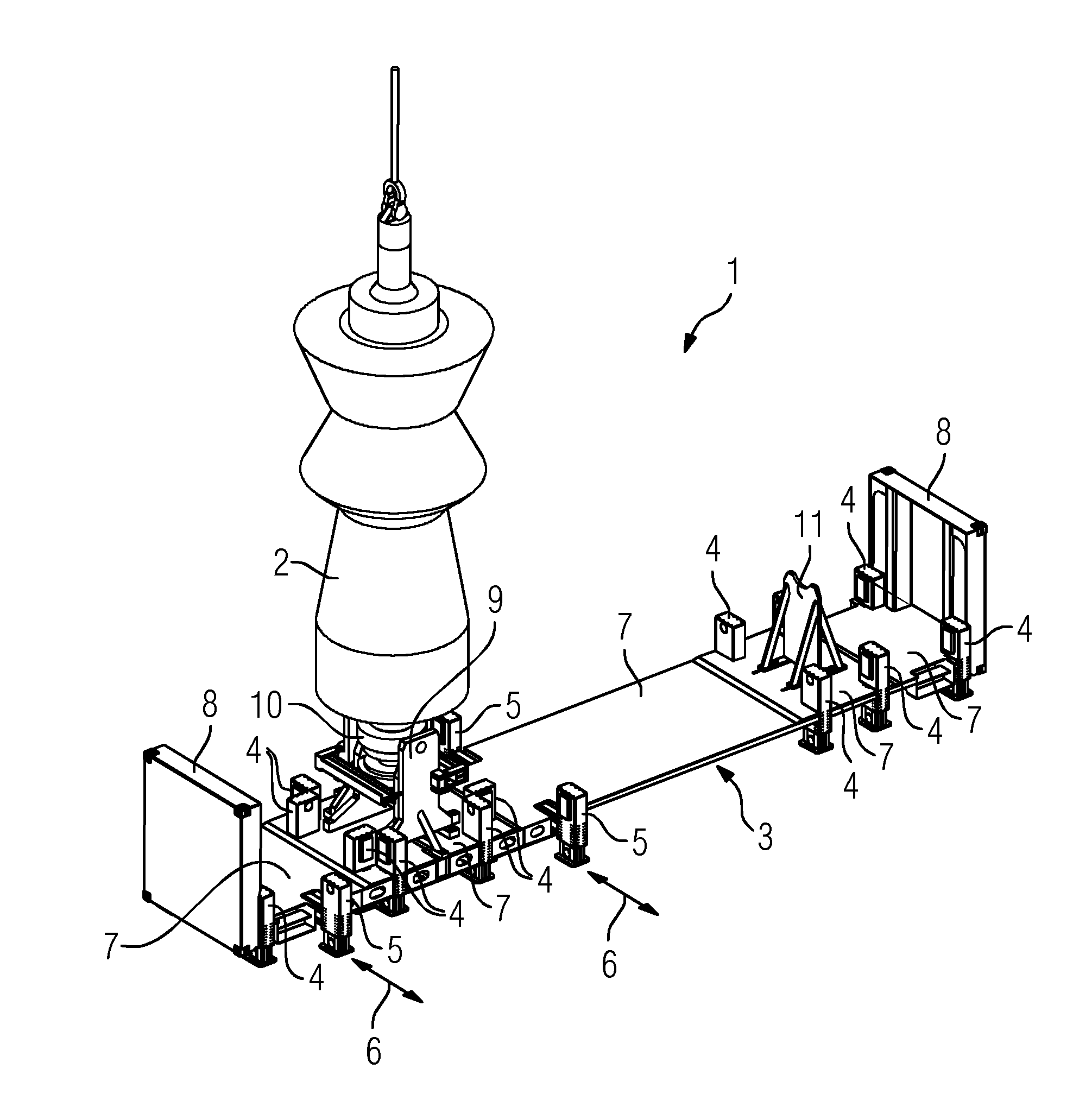
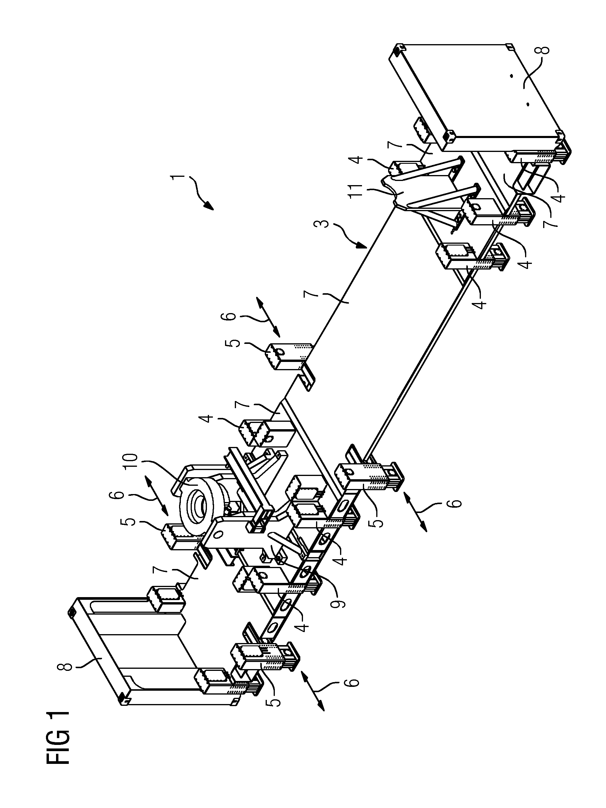
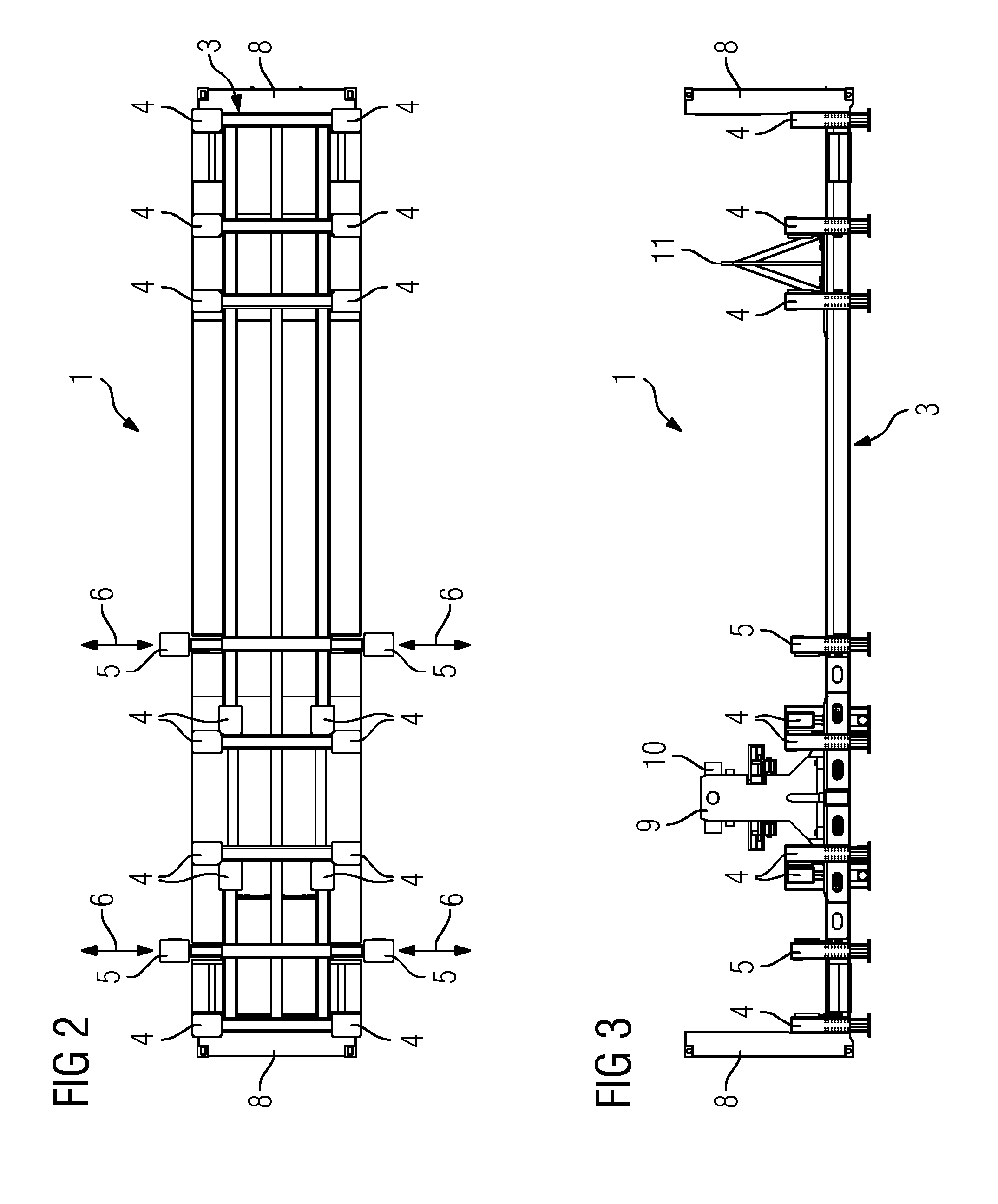
[0033]The Figures show a rotor pivoting system 1 according to an embodiment of the present invention, which serves for setting rotors upright, for example for setting a gas turbine rotor 2 upright. The rotor pivoting system 1 comprises a heavy-duty stand 3 which is provided with a multiplicity of vertically extendable supporting feet 4 and 5. Moreover, the supporting feet 5 are extendable horizontally in the direction of the arrows 6, in order, if required, to improve the steadiness of the heavy-duty stand 3. In this case, actuation of the supporting feet 4 and 5 takes place hydraulically, although, of course, alternative actuation variants will also be envisaged. The heavy-duty stand 3, may, for example, be a steel stand. A plurality of floorboards 7, which define a walk-on plane, are held on the stand. The heavy-duty stand has end walls 8 on its end faces. The dimensions of those walls are selected to correspond essentially to those of the end walls of a standard container, in the...


PUM

PropertyMeasurementUnit
Weightaaaaaaaaaa
Dimensionaaaaaaaaaa

Abstract

A rotor pivoting system (1) for setting a rotor (2) upright, for the purpose of maintenance and / or repair work: a turning pedestal (9) having a pivoting device (10), and at least one bearing pedestal (11) for supporting the rotor when not upright; a heavy-duty stand (3) with a multiplicity of vertically extendable supporting feet (4, 5) which receive the turning pedestal and the bearing pedestal and is transportable and introduces forces occurring when a rotor arranged on the turning pedestal (9) and the bearing pedestal (11) is being set upright, via the supporting feet (4, 5), into a base on which said stand is positioned. Also, a method for carrying out maintenance and / or repair work on a rotor (2) of a machine using a rotor pivoting system (1) according to the invention.

Description

CROSS-REFERENCE TO RELATED APPLICATIONS[0001]The present application claims priority of German Patent Application No. 102014200760.7, filed Jan. 17, 2014, the contents of which are incorporated by reference herein.BACKGROUND OF THE INVENTION[0002]The present invention relates to a rotor pivoting system for setting upright a rotor, in particular a gas turbine rotor, for the purpose of carrying out maintenance and / or repair work, the rotor pivoting system comprising a turning pedestal, having a pivoting device, and at least one bearing pedestal.[0003]Maintenance and / or repair work on a rotor are advantageously carried out while it is in a vertical position. In particular, the destacking of a gas turbine rotor is considerably simplified in this way. To set rotors having a high dead weight upright, rotor pivoting systems are employed in the prior art. These comprise a turning pedestal, with a pivoting device arranged on it, and at least one bearing pedestal. In a first step, the turning...

Claims


Application Information

Patent Timeline
IPC IPC(8): F01D25/28F01D5/00
CPCF01D25/285F01D5/005F05D2260/02F05D2230/80F05D2230/72F02C7/20F05D2250/411F05D2230/70F05D2230/68F05D2240/20Y10T29/49318B25H1/18B65D88/12B65D90/14B25H1/00F01D25/28F01D25/34F16M5/00
Inventor RICHTER, MATTHIASROCHLITZER, MARCUS
Owner SIEMENS AG
Why Eureka
Try Eureka