Radar apparatus

a technology of radar and apparatus, applied in the field of signal processing, can solve the problems that the controller that controls the vehicle may not perform proper control, and achieve the effects of reducing processing load, minimizing extrapolation process, and reducing processing load

Inactive Publication Date: 2015-07-23
FUJITSU GENERAL LTD
View PDF21 Cites 55 Cited by
  • Summary
  • Abstract
  • Description
  • Claims
  • Application Information

AI Technical Summary

Benefits of technology

[0015]According to one aspect of the invention, a radar apparatus is installed on a vehicle and is configured to receive a reflection wave reflected by a target and to derive a position of the target. The radar apparatus includes a signal processor configured to: derive a prediction peak signal in each of an up period in which a frequency of a transmission signal increases and in a down period in which the frequency of the transmission signal decreases, the frequency of the transmission signal changing in a predetermined cycle; set a prediction region having a predetermined range defined based on a prediction position of an angle peak signal, in each of the up period and the down period based on the prediction peak signal; determine whether or not a plurality of the angle peak signals exist in the prediction region in at least one of the up period and the down period; and (i) in a case where a first angle peak signal closest to the prediction position in the up period and a second angle peak signal closest to the prediction position in the down period satisfy a pairing condition, finalize a combination of the first angle peak signal and the second angle peak signal as a pair data set, and (ii) in a case where the combination of the first angle peak signal and the second angle peak signal does not satisfy the pairing condition, where the plurality of angle peak signals exist in the prediction region in at least one of the up period and the down period and where a different combination from the combination of the first angle peak signal and the second angle peak signal satisfies a re-pairing condition, finalize the different combination as the pair data set. Even in a case where the plurality of target data sets in the prediction region, the radar apparatus can finalize a combination of the angle peak signals having the highest possibility to be associated with a same reflection point, as the history pair data set. Thus, use of the extrapolation process can be reduced and an actual position of the target can be derived.
[0016]Moreover, according to another aspect of the invention, the signal processor is further configured to: determine whether or not the combination of the angle peak signals exists in a short distance range that is a range in a relatively short distance from the vehicle, in a current traffic lane region that is a range of a current traffic lane in which the vehicle is traveling, and wherein in a case where the combination of the angle peak signals exists in the current traffic lane region, the signal processor finalizes the different combination as the pair data set. The radar apparatus can reduce processing load caused by derivation of target information and can prevent from finalizing a wrong combination of an angle peak signal in the current traffic lane and an angle peak signal in a next traffic lane, as the pair data set. Therefore, an object of the invention is to provide a technology that minimizes the extrapolation process and that finalizes a combination of the angle peak signals having the highest possibility to be associated with a same reflection point, as a history pair data set.

Problems solved by technology

However, in the process of pairing the angle peak signals in the up period and the down period, in a case where the signal level difference between the angle peak signals exceeds the predetermined value, the radar apparatus does not finalize the combination of the peak signals as the history pair data set because in the case where the signal level difference between the angle peak signals in the up period and the down period in the pair exceeds the predetermined value, there is a high possibility that the angle peak signals in the combination are associated with different reflection points.
However, the extrapolation process is performed based on the prediction data set, not based on an actually derived data set.
Therefore, a derived position of the target may be different from an actual position so that the vehicle controller that controls the vehicle may not perform proper control in a case where the vehicle controller performs the vehicle control by obtaining position information of the target output from the radar apparatus.

Method used


Image

  • Radar apparatus
  • Radar apparatus
  • Radar apparatus

Examples


second embodiment

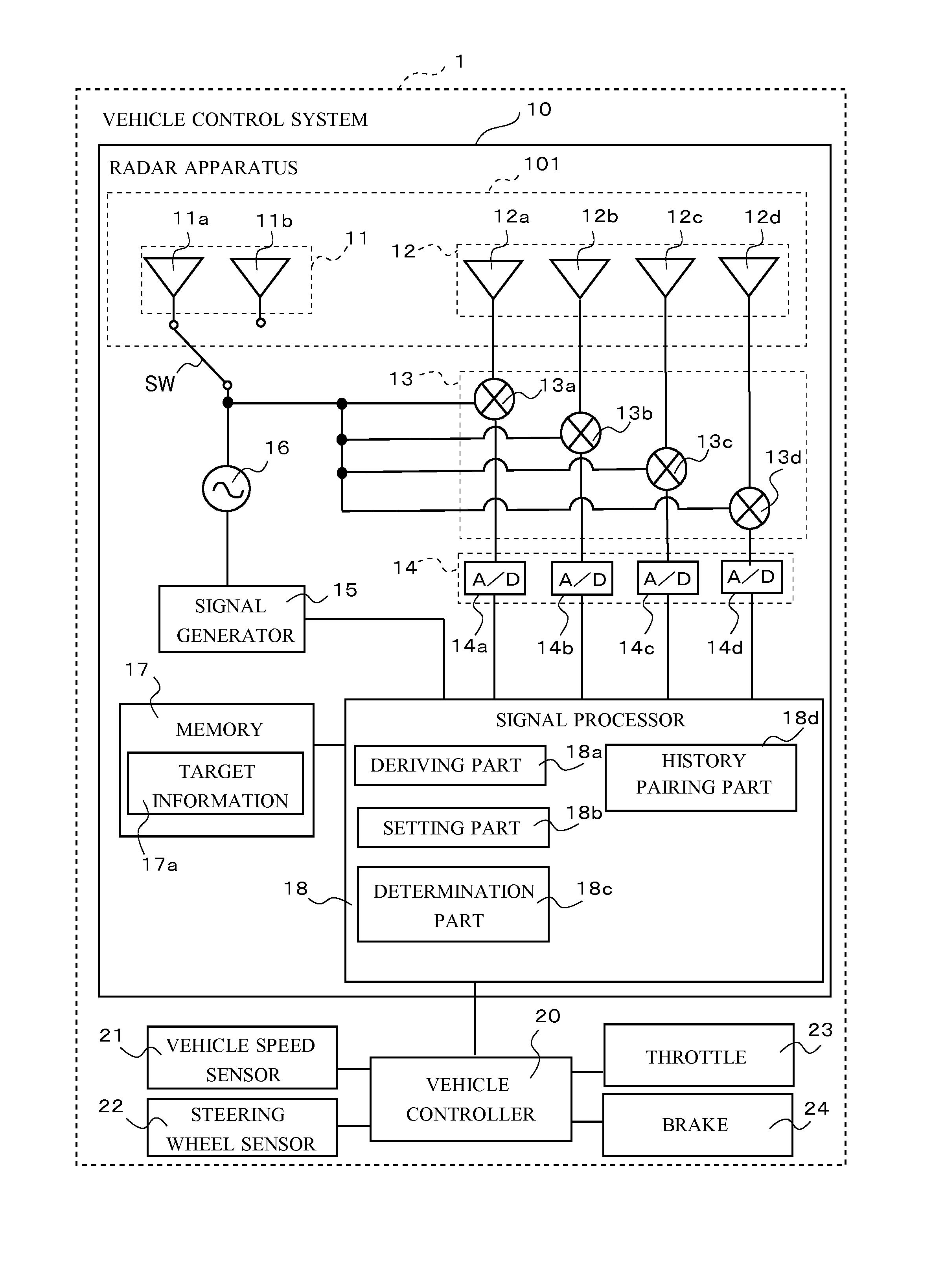
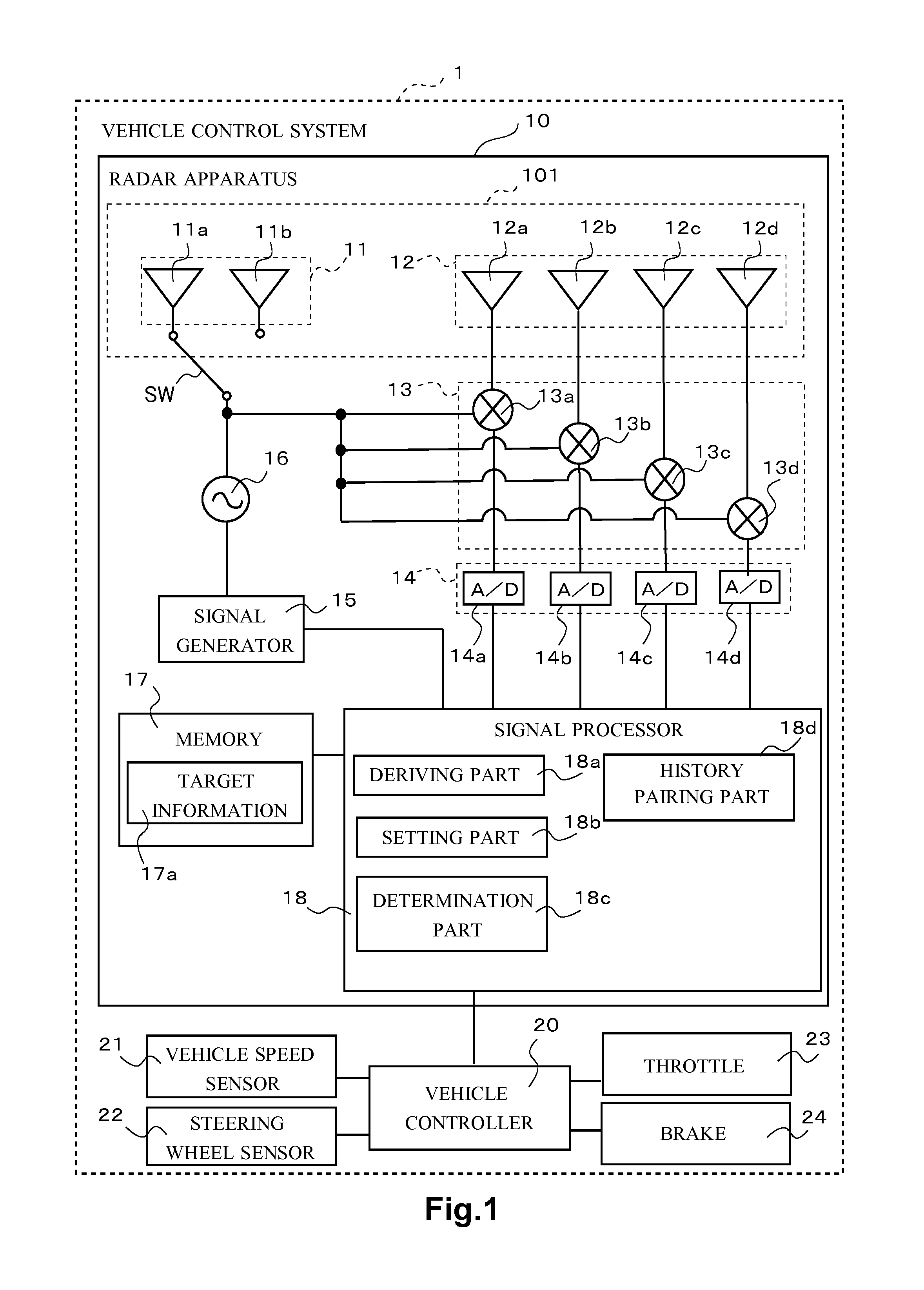
[0146]Next, a second embodiment is described. A signal processor 18 of a radar apparatus 10 in the second embodiment performs a process of finalizing a combination of angle peak signals as a history pair data set by reducing an angle range of a prediction region as a longitudinal distance of a target becomes greater, in the history pairing process explained in the first embodiment.

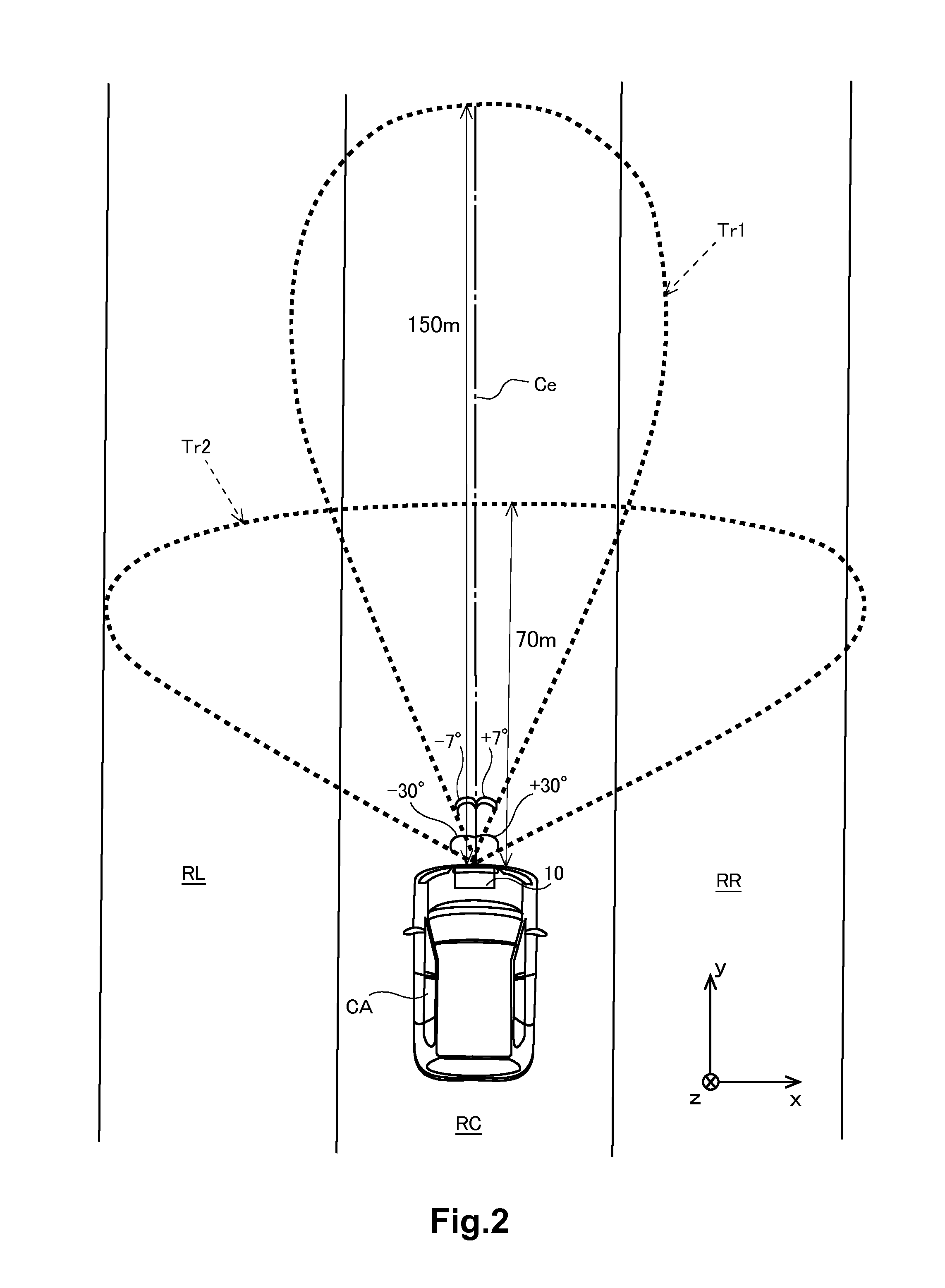
[0147]Generally, as the longitudinal distance becomes greater, a distance corresponding to a prediction angle range that is the angle range of the prediction region becomes greater. As the longitudinal distance becomes greater, even if the angle range is fixed (e.g. ±4 degrees), a lateral distance becomes greater. Thus, in a case where a target exists in a current traffic lane in a relatively long distance, a process of re-pairing of a different combination performed by a history pairing part 18d in the first embodiment may include an angle peak signal of a target existing outside a range of the current tr...

third embodiment

[0157]Next, a third embodiment is explained. In a case where an angle peak signal exists in a relatively short distance from a vehicle CA in a current traffic lane RC in which the vehicle CA is traveling, a signal processor 18 of a radar apparatus 10 in the third embodiment performs a process of re-pairing (the steps S135 to S137 in FIG. 10). In other words, in a case where the angle peak signal exists in a relatively long distance from the vehicle CA or in a case where the angle peak signal exists in at least one of a left next traffic lane RL and a right next traffic lane RR but does not exist in the current traffic lane RC in which the vehicle CA is traveling, the signal processor 18 does not perform the process of re-pairing but performs only the process of history pairing based on the Mahalanobis distance. Due to those processes, the signal processor 18 can reduce processing load caused by derivation of target information and can prevent from finalizing a wrong combination of t...

fourth embodiment

[0168]Next a fourth embodiment is explained. A signal processor 18 of a radar apparatus 10 in the fourth embodiment selects only an angle peak signal existing in a range of a current traffic lane defined based on a relative lateral distance, as an object signal for re-pairing in the history pairing process described in the first embodiment.

[0169]Concretely, the signal processor 18 obtains a radius value of a curve relating to a current traffic lane RC in which a vehicle CA is traveling, from a vehicle controller 20. The radius value of the curve is derived by the vehicle controller 20 based on a rotation angle of a steering wheel sensor 22. The radius value of the curve may be derived in a different method, for example, based on an image captured by a camera. The signal processor 18 calculates a relative lateral distance of the angle peak signal based on the radius of the curve and selects the angle peak signal of which the relative lateral distance is in the current traffic lane RC...


PUM


Abstract

A radar apparatus includes a signal processor configured to: (i) in a case where a first angle peak signal closest to a prediction position in an up period and a second angle peak signal closest to the prediction position in a down period satisfy a pairing condition, finalize a combination of the first angle peak signal and the second angle peak signal as a pair data set; and (ii) in a case where the combination of the first angle peak signal and the second angle peak signal does not satisfy the pairing condition, where the plurality of angle peak signals exist in the prediction region in at least one of the up period and the down period and where a different combination from the combination of the first angle peak signal and the second angle peak signal satisfies a re-pairing condition, finalize the different combination as the pair data set.

Description

BACKGROUND OF THE INVENTION[0001]1. Field of the Invention[0002]The invention relates to a signal process that is used to derive a position of a target.[0003]2. Description of the Background Art[0004]Conventionally, a radar apparatus mounted on a vehicle sends a transmission wave from a transmitting antenna and a receiving antenna of the radar apparatus receives a reflection wave that is the transmission wave reflected at a point on an object (hereinafter referred to as “target”). Accordingly, the radar apparatus derives information of the target (hereinafter referred to as “target information”), including a position of the target relative to the vehicle.[0005]Concretely, the radar apparatus generates a beat signal by mixing a reception signal and a transmission signal of which a frequency changes in a predetermined cycle. Then the radar apparatus processes the beat signal by using fast Fourier transform (FFT) to generate a frequency spectrum. A signal exceeding a predetermined thre...

Claims


Application Information

Patent Timeline
Patent Type & Authority Applications(United States)
IPC IPC(8): G01S13/06B60W30/00G01S13/931
CPCB60W30/00G01S13/06G01S13/345G01S13/42G01S13/584G01S13/931G01S2013/93271G01S2013/932
Inventor YOSHIMURA, KEISHIISHIMORI, HIROYUKI
Owner FUJITSU GENERAL LTD
Why Eureka
Try Eureka