Lens barrel

a technology of an imaging apparatus and a barrel, which is applied in the direction of printers, instruments, camera focusing arrangement, etc., can solve the problems of particularly unsuitable arrangement, and achieve the effect of free arrangement (positions)

Inactive Publication Date: 2015-07-23
HOYA CORP
View PDF1 Cites 6 Cited by
  • Summary
  • Abstract
  • Description
  • Claims
  • Application Information

AI Technical Summary

Benefits of technology

[0013]In order to address the above-described demands, the present invention provides a lens barrel including a first drive system (first drive mechanism) that uses a cam mechanism and a second drive system (second drive mechanism) that uses a feed screw and a nut, in which the freedom in the arr

Problems solved by technology

However, in such an arrangement, a problem exists with the size (the length in the optical axis direction in particular) of the lens barrel increasing in order to obtain a large amount of movement space for each lens group; hence, such arrangement is especially unsuitable for a lens barrel which retracts (shortens its length) in order to be accommodated

Method used


Image

  • Lens barrel
  • Lens barrel
  • Lens barrel

Examples


Embodiment Construction

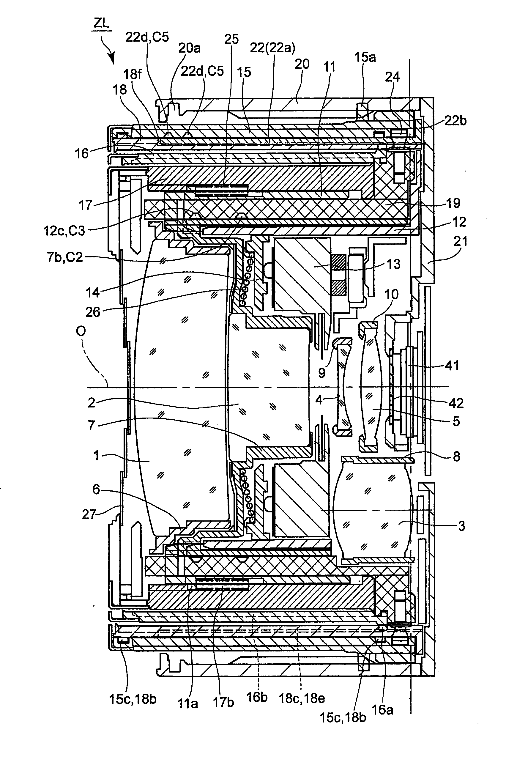
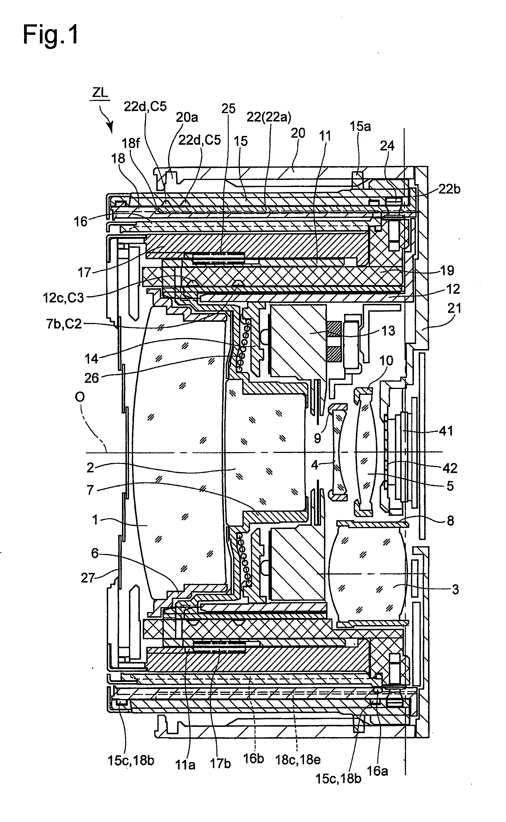
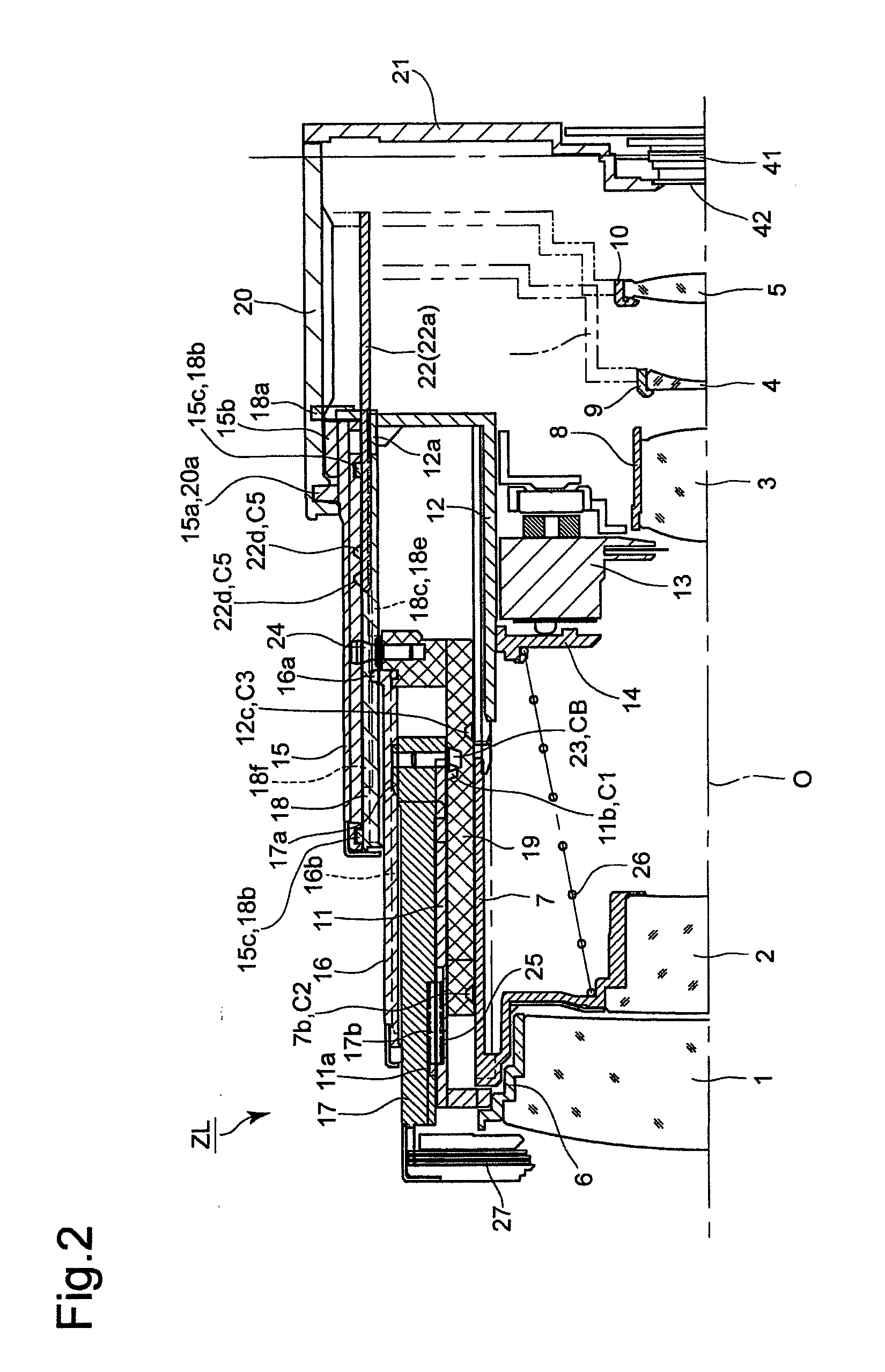
[0043]An embodiment of the present invention will be discussed below with reference to the drawings. A zoom lens barrel ZL of the embodiment shown in FIGS. 1 through 3 showing the overall configuration thereof is mounted onto a camera body (not shown). The photographing optical system of the zoom lens barrel ZL is configured of a first lens group 1, a second lens group 2, a third lens group 3, a fourth lens group 4, a fifth lens group 5, an optical filter 42, and an image sensor 41, in that order from the object side. Each lens group is shown in the drawings as a single lens element even in the case of a lens group being configured of a plurality of lens elements. In the following descriptions, a direction toward the object side along an optical axis O of the photographing optical system designates a forward optical axis direction, and a direction toward the image side along the optical axis O designates a rearward optical axis direction.

[0044]The zoom lens barrel ZL can be driven (...


PUM


Abstract

A lens barrel includes a first drive mechanism which rotates a cam ring to move a cam-driven lens frame, holding a lens group, in accordance with a cam groove; a second drive mechanism which screw-engages a nut with a feed screw, biases a nut-driven lens frame to abut the nut, and moves the nut-driven lens frame. The cam-driven lens frame is positioned adjacent to the nut-driven lens frame on a reverse side to the biasing direction, and driving ranges of these lens frames partially overlap each other. The first drive mechanism includes a cam-driven member, separate from the cam-driven lens frame, which is linearly guided and provided with a cam follower which engages with the cam groove of the cam ring; and a biasing member which biases the cam-driven lens frame to abut against the cam-drive member, so that the cam-driven lens frame moves with the cam-driven member.

Description

BACKGROUND OF THE INVENTION[0001]1. Field of the Invention[0002]The present invention relates to a lens barrel of an imaging apparatus, and in particular, relates to a drive mechanism for moving (driving) a lens group that constitutes a photographing optical system in an optical axis direction thereof.[0003]2. Description of the Related Art[0004]In a lens barrel provided with at least one lens group, of a photographing optical system, which is moved in an optical axis direction thereof to carry out a zooming operation and / or a focusing operation, there have been numerous countermeasures taken in order to prevent damage and / or breakage of the lens group and the drive mechanism therefor even in the case where a mechanical or control error of some kind occurs during the driving (moving) of the lens group.[0005]One known example of such a countermeasure, in a lens barrel provided with a first drive system which controls the position of a lens support frame via a cam mechanism, provided ...

Claims


Application Information

Patent Timeline
IPC IPC(8): G02B7/10G03B3/10
CPCG03B3/10G02B7/10G02B7/102G03B5/00G03B2205/00
Inventor SASAKI, TAKAMITSU
Owner HOYA CORP
Why Eureka
Try Eureka