Controlled polymeric material conductivity for use in a two-phase electrode layer
What is AI technical title?
AI technical title is built by Patsnap AI team. It summarizes the technical point description of the patent document.
a polymer material and conductivity control technology, applied in the field of electrophoretic displays, can solve the problems of inadequate service life of these displays, unable to meet the needs of use, and gas-based electrophoretic media are susceptible to the same types of problems, and achieve the effect of less conductivity
Active Publication Date: 2015-07-23
E INK CORPORATION
View PDF6 Cites 51 Cited by
Summary
Abstract
Description
Claims
Application Information
AI Technical Summary
This helps you quickly interpret patents by identifying the three key elements:
Problems solved by technology
Method used
Benefits of technology
Benefits of technology
This patent describes an electro-optic display that uses a two-phase electrode layer made of a highly conductive matrix and a polymeric material with controlled resistivity. The polymeric material can be a conductive polymer or a mixture of a conductive polymer and an additive. The additive can be a salt, a polyelectrolyte, a polymerelectrolyte, a solid electrolyte, or a combination of these. The polymeric material can also contain conducting polymers such as PEDOT-PSS or polyacetylene. The second phase can be an ionic conductive polymer in which one ion can migrate through the polymer while the other cannot. The polymeric material can also contain a low number average molecular weight polymer containing hydroxyl. The electro-optic assembly includes first and second substrates, an adhesive layer, and a layer of electro-optic material disposed between the first and second substrates. The two-phase electrode layer can be used in a front plane laminate or an electro-optic assembly.
Problems solved by technology
Nevertheless, problems with the long-term image quality of these displays have prevented their widespread usage.
For example, particles that make up electrophoretic displays tend to settle, resulting in inadequate service-life for these displays.
Such gas-based electrophoretic media appear to be susceptible to the same types of problems due to particle settling as liquid-based electrophoretic media, when the media are used in an orientation which permits such settling, for example in a sign where the medium is disposed in a vertical plane.
Indeed, particle settling appears to be a more serious problem in gas-based electrophoretic media than in liquid-based ones, since the lower viscosity of gaseous suspending fluids as compared with liquid ones allows more rapid settling of the electrophoretic particles.
Such films comprise regions of high conductivity surrounded by regions of significantly less conductivity, which may accumulate electrical charges and disrupt the performance of the electro-optical display.
Method used
Image
Click on the blue label to locate the original text in one second.
Reading with bidirectional positioning of images and text.
Examples
Embodiment Construction
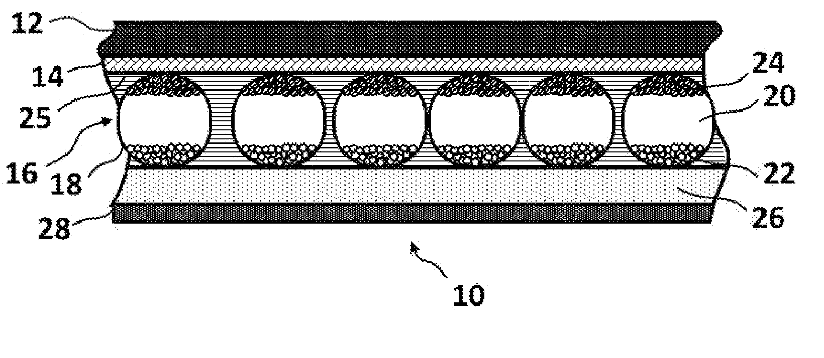
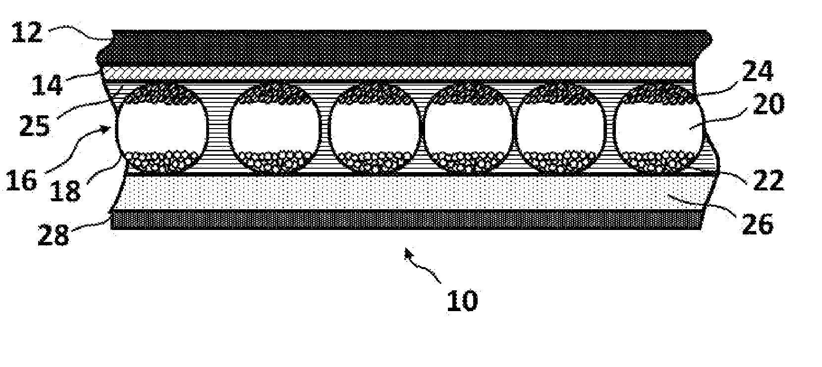
[0038]Accordingly, this invention provides an electro-optic display comprising a two-phase, light-transmissive electrically-conductive layer containing a first phase made from a highly conductive matrix and a second phase made from a polymeric material composition having a controlled volume resistivity. An electro-optic display normally comprises a layer of electro-optic material and at least two other layers disposed on opposite sides of the electro-optic material, at least one of these being a light-transmissive electrically-conductive layer. The term “light-transmissive” is used herein to mean that the layer thus designated transmits sufficient light to enable an observer, looking through that layer, to observe the change in display states of the electro-optic medium, which will be normally be viewed through the electrically-conductive layer and adjacent substrate (if present).
[0039]The first phase may be a conductive matrix. The term “conductive matrix” is used herein to describ...
PUM
Property
Measurement
Unit
diameter
aaaaa
aaaaa
thickness
aaaaa
aaaaa
thickness
aaaaa
aaaaa
Abstract
An electro-optic display containing a two-phase, light-transmissive electrically-conductive layer comprising a first phase made of a highly electronically-conductive matrix and a second phase made of a polymeric material composition having a controlled volume resistivity. The matrix of the first phase may be formed from carbon nanotubes, silver nanowires, a metal coated open foam structure, or a printed mesh of wires. The polymeric material composition of the second phase may be a conductive polymer, or a polymer and an additive such as a salt, a polyelectrolyte, a polymerelectrolyte, or a solidelectrolyte, or combinations thereof.
Description
REFERENCE TO RELATED APPLICATIONS[0001]This application is related to:[0002](a) U.S. Pat. No. 7,012,735, filed Mar. 26, 2004;[0003](b) U.S. Pat. No. 7,349,148, filed Dec. 20, 2006, which is a divisional of U.S. Pat. No. 7,173,752, field Nov. 5, 2004;[0004](c) U.S. Pat. No. 8,446,664, filed Apr. 4, 2011; and[0005](b) copending U.S. application Ser. No. 12 / 264,696, filed Nov. 4, 2008 (Publication No. 2009 / 0122389 A1).[0006]The entire contents of these patents and copending applications, and of all other U.S. patents and published and copending applications mentioned below, are herein incorporated by reference.BACKGROUND OF INVENTION[0007]This invention relates to electro-optic displays and, more specifically, to electro-optic assemblies containing a two-phase, light-transmissive electrically-conductive layer comprising a first phase made of a highly electronically-conductive matrix and a second phase made of a polymeric material composition having a controlled volume resistivity. In a...
Claims
Application Information
Patent Timeline
Application Date:The date an application was filed.
Publication Date:The date a patent or application was officially published.
First Publication Date:The earliest publication date of a patent with the same application number.
Issue Date:Publication date of the patent grant document.
PCT Entry Date:The Entry date of PCT National Phase.
Estimated Expiry Date:The statutory expiry date of a patent right according to the Patent Law, and it is the longest term of protection that the patent right can achieve without the termination of the patent right due to other reasons(Term extension factor has been taken into account ).
Invalid Date:Actual expiry date is based on effective date or publication date of legal transaction data of invalid patent.
Patent Type & AuthorityApplications(United States)

