Respiratory assistance device, nasal appliance and respiratory assistance mask
Inactive Publication Date: 2015-07-30
BOUSSIGNAC GEORGES
View PDF2 Cites 2 Cited by
Summary
Abstract
Description
Claims
Application Information
AI Technical Summary
This helps you quickly interpret patents by identifying the three key elements:
Problems solved by technology
Method used
Benefits of technology
Benefits of technology
The patent describes a device that helps ventilate patients by delivering air or other gases through a secure hole in the device. The device uses fibrous or porous material to mask the noise of the air jets passing through. The device also includes a device for detecting the patient's breathing and a controllable valve that helps the patient inhale air or gases under a higher pressure. The valve closes during expirations and opens during inhalations. The technical effects of this invention are improved ventilation for patients and reduction of noise and discomfort during ventilation.
Problems solved by technology
However, the device such as it has been proposed has the inconvenience of generating a certain noise due to the injection of air which creates turbulences inside the device and since the latter is open.
That simple solution implies however the inconvenient of making that device more complex or of adding an accessory to the device.
Indeed, the value “5” of “5 to 800 microns” in those documents does not allow for producing a practically usable device, since between three and nine auxiliary channels only are foreseen (cf.
Method used
Image
Click on the blue label to locate the original text in one second.
Reading with bidirectional positioning of images and text.
Examples
embodiment 1
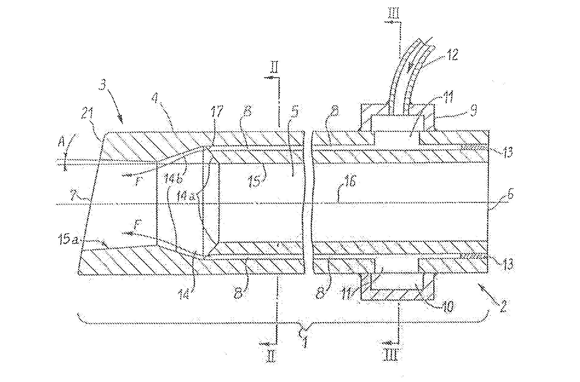
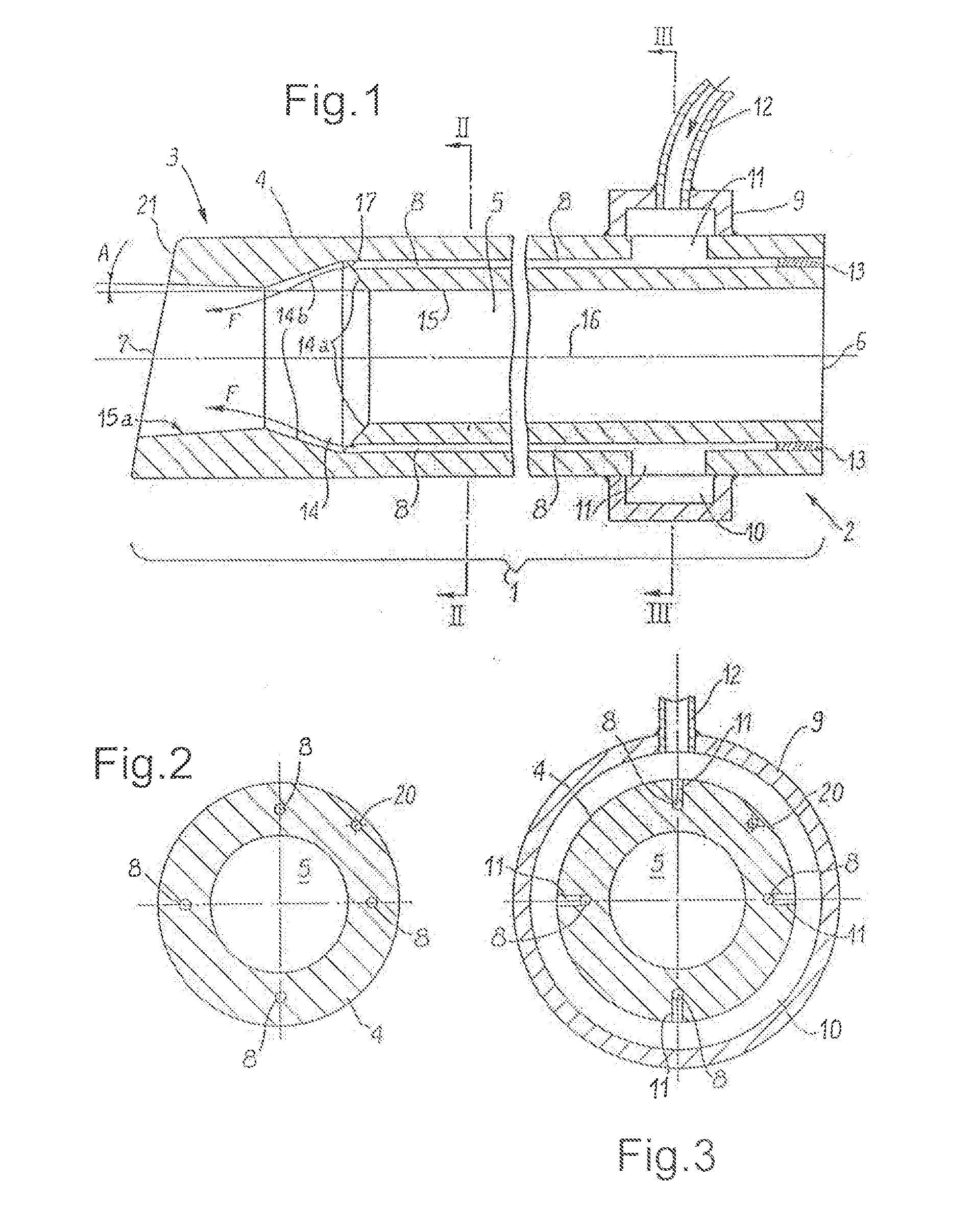
[0207]On FIG. 1, which is a diagrammatic view at a large scale, a tubular element is represented with its proximal end 2 and its distal end 3 of the device according to the invention. That embodiment can constitute or be combined with, for example, an endotracheal probe, an oro-nasal probe with or without a balloon, an endotracheal paediatric probe, a monitoring probe for gases, an endobronchial probe, a nasopharyngeal probe, an anatomic intubation probe for children, a neonatal Cole probe, a cannula type Guedel probe, or a nasal probe for oxygen therapy.
[0208]The device 1 comprises a tubular element 4, which is supple or preformed, especially for adapting itself to the morphology of the patient, surrounding a main channel 5 which ends, by means of its proximal opening 6, at the proximal end 2 and, by means of its distal opening 7, at the distal end 3.
[0209]Thus, the main channel 5 is able to ensure a passage way between the openings 6 and 7, one of which, the distal opening 7, is i...
embodiment 22
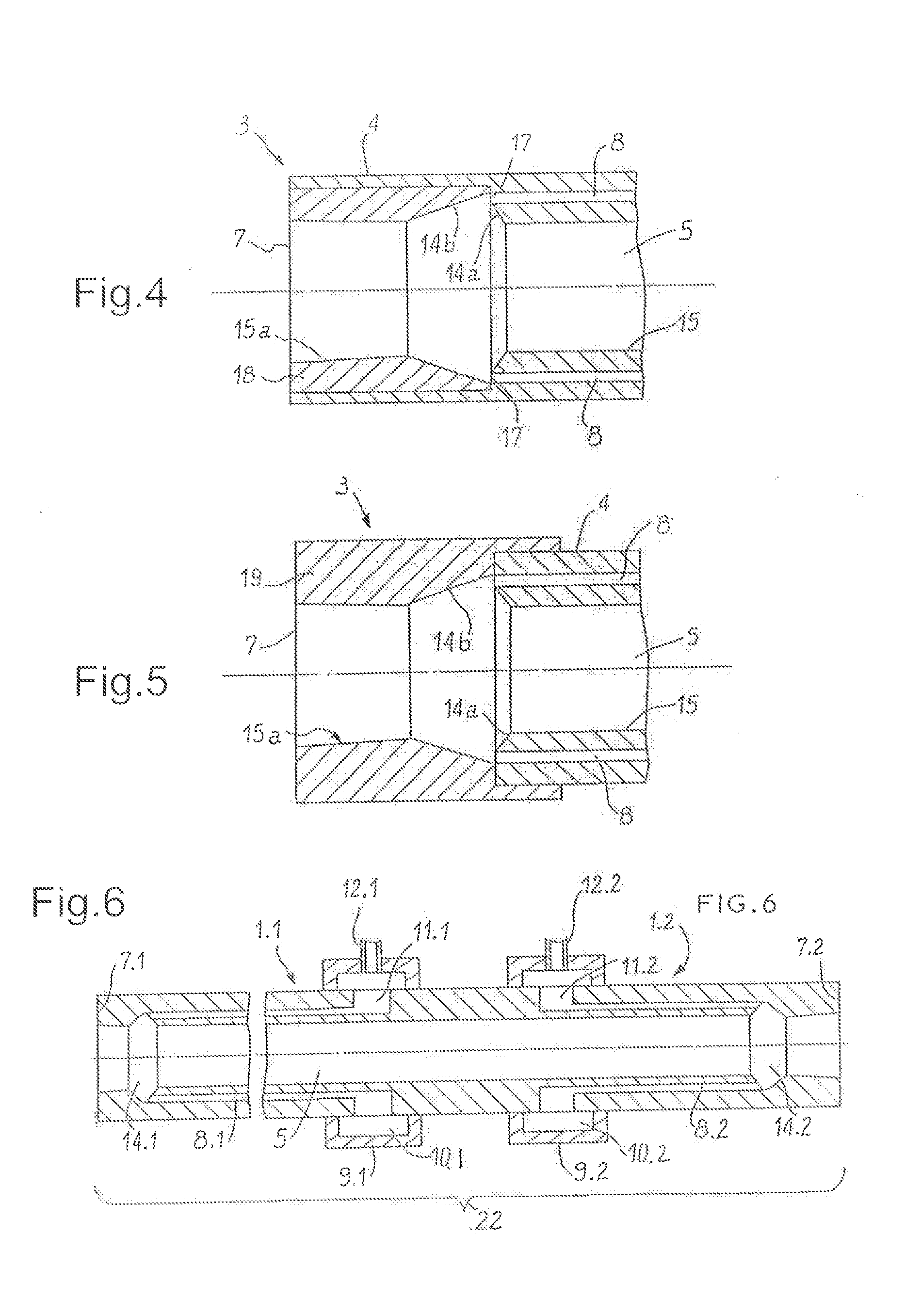
[0231]The variant 22 of the embodiment of the device according to the invention, which is with two inverted flows, shown on FIG. 6, comprises two devices 1.1 and 1.2, each having a structure similar to the one of FIG. 1, which are inverted and put together at their proximal ends, the device 1.2 may then be shorter than the device 1.1. In that variant of embodiment 22, the distal hole (at the side of the patient) of the device is constituted by the distal opening 7.1 of device 1.1, whereas the proximal hole (opposite the patient) is formed by the opening 7.2 of device 1.2. Each one of the devices 1.1 and 1.2 is provided with its supply system 9.1, 9.2, 10.1, 10.2, 11.1, 11.2, and 12.1, 12.2 for pressurized respirable gas, supplying the respective channels 8.1 or 8.2, leading to / opening-out in the annular holes 14.1 or 14.2, respectively close to said openings 7.1 and 7.2. The device 22 forms a two-reverse-flow probe. That device being placed on the patient, i.e. the device 1.1 being ...
PUM
Abstract
A device for respiratory assistance of a patient includes a tubular element forming a main channel for connection by its distal end to a respiratory tract of the patient, the main channel connecting the patient's respiratory system by its proximal end to the outside, the device further including at least one auxiliary channel for injecting a jet or jets of respirable gas through one or more distal outlet holes of the auxiliary channel or channels, the one or more outlet holes opening-out in the main channel in the vicinity of the distal end of the latter, deflecting elements for deflecting the jets of respirable gas toward the interior of the main channel. The diameter of the outlet hole of each auxiliary channel is less than 150 microns. The outlet holes of the device are shaped as an annular or semi annular strip resulting from assembling / uniting together certain distal outlet holes.
Description
FIELD OF THE INVENTION[0001]The present invention relates to an improved device for respiratory assistance to be used on patients whose spontaneous respiration is absent or insufficient, whether or not they are placed under artificial respiration. It is particularly well adapted to the devices for respiratory assistance invented by Mister Georges BOUSSIGNAC.BACKGROUND OF THE INVENTION[0002]The principle that the device for respiratory assistance invented by Mister BOUSSIGNAC is based on consists in injecting at least one pressurized respirable gas via a plurality of auxiliary channels into the lumen of a tube connected to the respiratory tract of the patient. That device for assistance is particular in being of the so-called open type, which means that the tube can remain open to the ambient air allowing thus for passing probes or other accessories, called herein after the ancillaries, for survey or treatment of the patient. More precisely, the device for assistance is formed from a...
Claims
Application Information
Patent Timeline
Application Date:The date an application was filed.
Publication Date:The date a patent or application was officially published.
First Publication Date:The earliest publication date of a patent with the same application number.
Issue Date:Publication date of the patent grant document.
PCT Entry Date:The Entry date of PCT National Phase.
Estimated Expiry Date:The statutory expiry date of a patent right according to the Patent Law, and it is the longest term of protection that the patent right can achieve without the termination of the patent right due to other reasons(Term extension factor has been taken into account ).
Invalid Date:Actual expiry date is based on effective date or publication date of legal transaction data of invalid patent.

