Torsional coupling for electric hydraulic fracturing fluid pumps

a technology of hydraulic fracturing fluid and torsional coupling, which is applied in the direction of piston pumps, positive displacement liquid engines, borehole/well accessories, etc., can solve the problems of u-joint shaft use, inefficiency in the system, and loss of up to 10% or more of the energy that would otherwise be transmitted from the motor sha

Active Publication Date: 2015-07-30
US WELL SERVICS LLC
View PDF20 Cites 66 Cited by
  • Summary
  • Abstract
  • Description
  • Claims
  • Application Information

AI Technical Summary

Benefits of technology

[0015]In some embodiments, the torsional coupling can further include a retainer cap attached to the motor component or the hydraulic fracturing equipment component to cover the interface therebetween and to pr...

Problems solved by technology

Use of U-joint shafts, however, can be problematic in practice.
For example, U-joint shafts introduce inefficiencies into the system, losing up to 10% or more of the energy that would otherwise be transmitted from the motor shaft to the equipment.
This offset le...

Method used


Image

  • Torsional coupling for electric hydraulic fracturing fluid pumps
  • Torsional coupling for electric hydraulic fracturing fluid pumps
  • Torsional coupling for electric hydraulic fracturing fluid pumps

Examples


Embodiment Construction

[0032]The foregoing aspects, features, and advantages of the present technology will be further appreciated when considered with reference to the following description of preferred embodiments and accompanying drawing, wherein like reference numerals represent like elements. In describing the preferred embodiments of the technology illustrated in the appended drawing, specific terminology will be used for the sake of clarity. However, the technology is not intended to be limited to the specific terms used, and it is to be understood that each specific term includes equivalents that operate in a similar manner to accomplish a similar purpose.

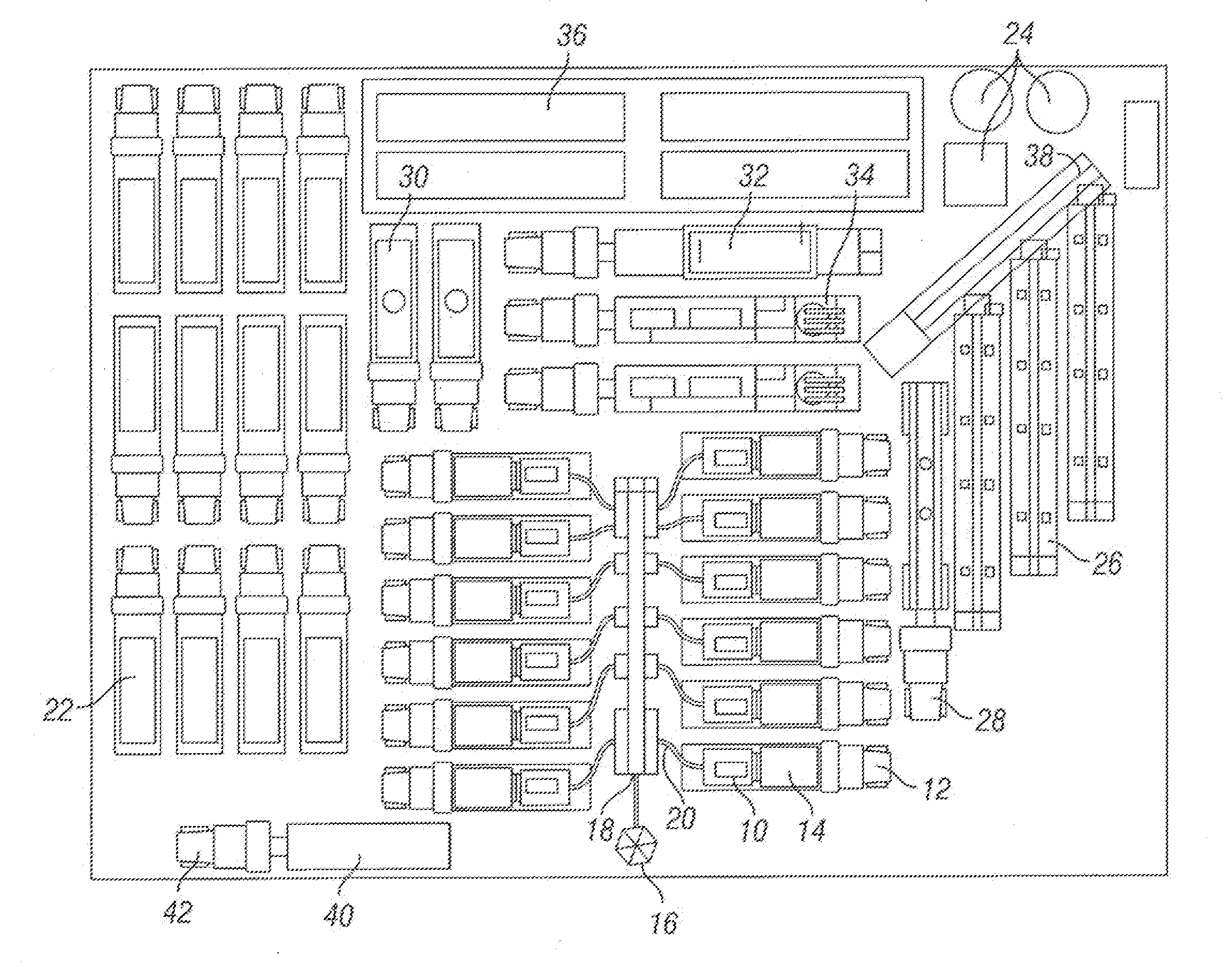
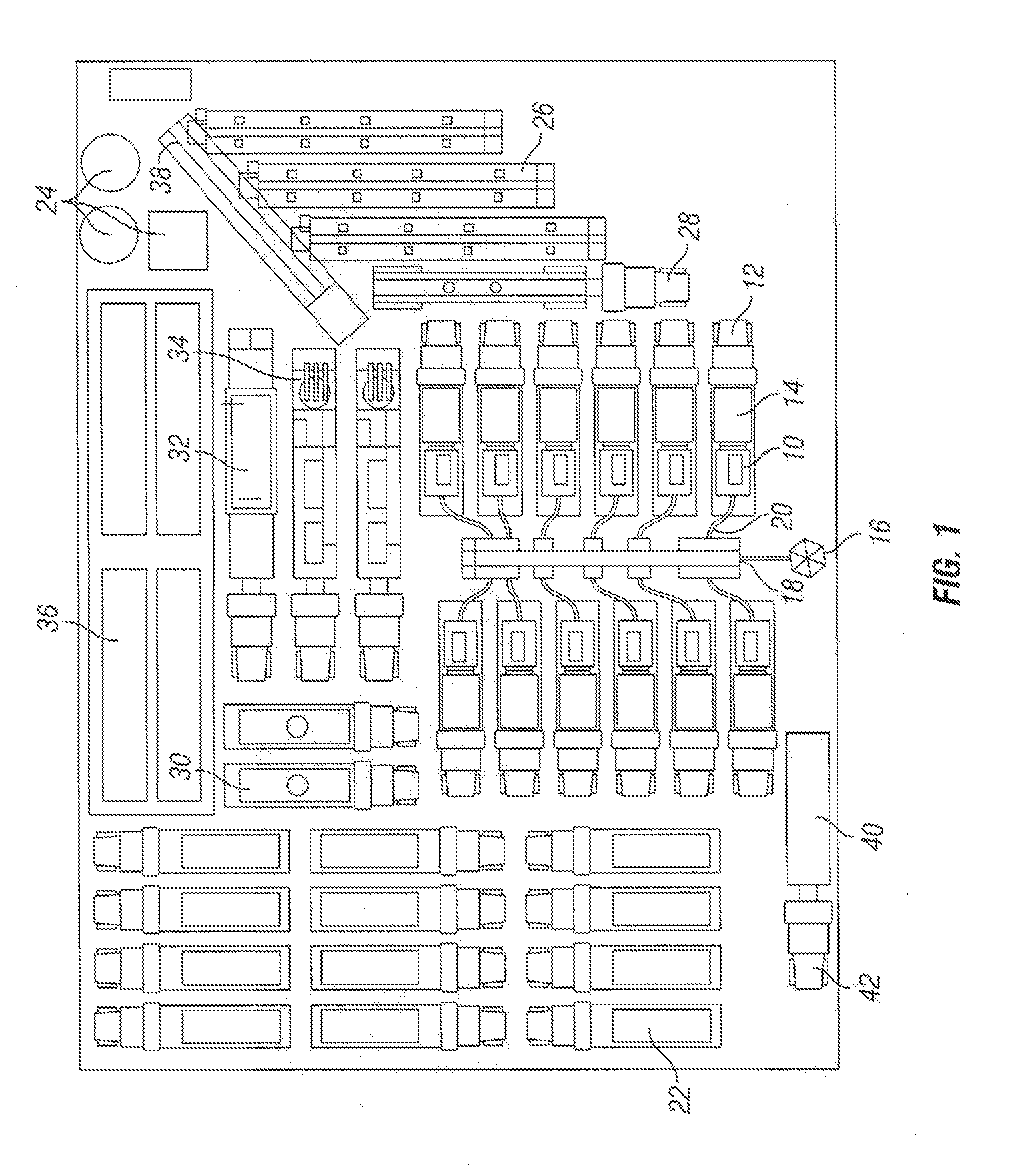
[0033]FIG. 1 shows a plan view of equipment used in a hydraulic fracturing operation. Specifically, there is shown a plurality of pumps 10 mounted to vehicles 12, such as trailers (as shown, for example, in FIGS. 3 and 4). In the embodiment shown, the pumps 10 are powered by electric motors 14, which can also be mounted to the vehicles 12. The pu...


PUM


Abstract

A system for hydraulically fracturing an underground formation in an oil or gas well, including a pump for pumping hydraulic fracturing fluid into the wellbore, the pump having a pump shaft, and an electric motor with a motor shaft mechanically attached to the pump to drive the pump. The system further includes a torsional coupling connecting the motor shaft to the pump shaft. The torsional coupling includes a motor component fixedly attached to the motor shaft and having motor coupling claws extending outwardly away from the motor shaft, and a pump component fixedly attached to the pump shaft of the pump and having pump coupling claws extending outwardly away from the pump shaft. The motor coupling claws engage with the pump coupling claws so that when the motor shaft and motor component rotate, such rotation causes the pump component and the pump shaft to rotate, thereby driving the pump.

Description

CROSS-REFERENCE TO RELATED APPLICATIONS[0001]This application is a continuation-in-part of, and claims priority to and the benefit of, U.S. patent application Ser. No. 13 / 679,689, which was filed Nov. 16, 2012, the full disclosure of which is incorporated herein by reference.BACKGROUND OF THE INVENTION[0002]1. Field of the Invention[0003]This technology relates to hydraulic fracturing in oil and gas wells. In particular, this technology relates to pumping fracturing fluid into an oil or gas well using pumps powered by electric motors.[0004]2. Brief Description of Related Art[0005]Typically, motors are used at a well site to drive equipment. For example, diesel, gas, or electric motors might be used to drive pumps, blenders, or hydration units for carrying out hydraulic fracturing operations. Such motors are attached to the well site equipment by connecting the shaft of the motor to a shaft on the equipment, such a pump shaft for a pump, or a hydraulic motor shaft for a blender or a ...

Claims


Application Information

Patent Timeline
IPC IPC(8): F04D13/06E21B43/26
CPCE21B43/26F04D13/06F04D29/044F04B9/02F04B17/03F04B47/00E21B43/2607F04D29/66
Inventor BROUSSARD, JOEL N.MCPHERSON, JEFFKURTZ, ROBERTOEHRING, JARED
Owner US WELL SERVICS LLC
Why Eureka
Try Eureka