Warning device and method for monitoring alarm status of a vibration level of a piece of rotating machinery having an adaptive alarm indicator

a technology of alarm indicator and alarm status, which is applied in the direction of vibration measurement in solids, instruments, structural/machine measurement, etc., can solve the problems of high installation cost, large amount of power consumption, and high cost of wired indicators to line power, so as to maximize the visibility of indicators at initial indication

Inactive Publication Date: 2015-07-30
AB SKF
View PDF8 Cites 10 Cited by
  • Summary
  • Abstract
  • Description
  • Claims
  • Application Information

AI Technical Summary

Benefits of technology

[0037]controlling the at least one colored light indicator with the control unit to blink at a relatively quick initial rate and / or intensity that maximizes indicator visibility at initial indication;
[0039]extending power source life of operation by virtue of the relatively decreasing blink rate from initial indication over time is achieved.

Problems solved by technology

Also, a major consideration is the installation cost, especially for cabling.
Most machine condition indicators (MCI's) found in industrial environments are line powered and can afford to consume a significant amount of power while indicating an alarm status.
However, it is expensive to wire all indicators to line power and line power is not always easy to access.

Method used


Image

  • Warning device and method for monitoring alarm status of a vibration level of a piece of rotating machinery having an adaptive alarm indicator
  • Warning device and method for monitoring alarm status of a vibration level of a piece of rotating machinery having an adaptive alarm indicator
  • Warning device and method for monitoring alarm status of a vibration level of a piece of rotating machinery having an adaptive alarm indicator

Examples


Embodiment Construction

[0050]The following detailed description is merely exemplary in nature and is not intended to limit the described embodiments or the application and uses of the described embodiments. As used herein, the word “exemplary” or “illustrative” means “serving as an example, instance, or illustration.” Any implementation described herein as “exemplary” or “illustrative” is not necessarily to be construed as preferred or advantageous over other implementations. All of the implementations described below are exemplary implementations provided to enable persons skilled in the art to make or use the embodiments of the disclosure and are not intended to limit the scope of the disclosure, which is defined by the claims.

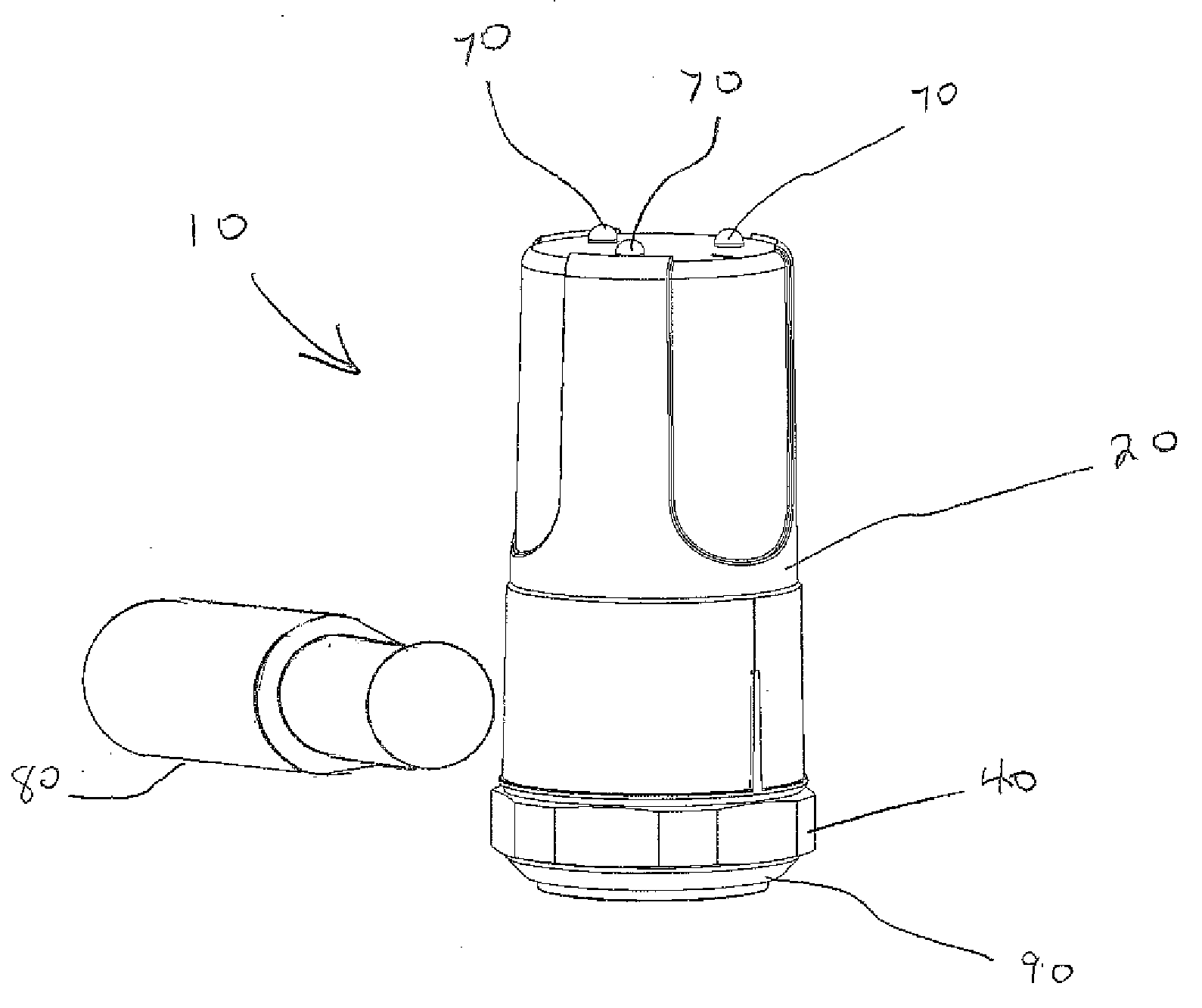
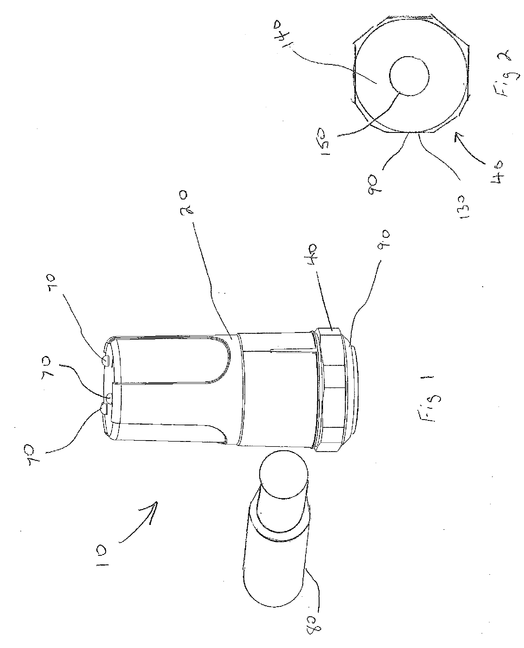
[0051]For purposes of description herein, the terms “upper,”“lower,”“left,”“rear,”“right,”“front,”“vertical,”“horizontal,” and derivatives thereof shall relate to the invention as oriented in FIG. 1. Furthermore, there is no intention to be bound by any expressed or implied theory...


PUM


Abstract

A warning device apparatus for monitoring an alarm status of a bearing that is mounted to a piece of rotating machinery is provided. The warning device includes a body portion, a top portion, a base portion, a power source for powering the device throughout a life of operation, a controller for controlling the operation of the warning device and at least one LED for displaying the alarm status. An operator inspects the warning device for an initial alarm indication by visually inspecting the at least one LED. The at least one LED is controlled to blink at a relatively quick initial rate and / or intensity that maximizes indicator visibility to the operator at initial indication. The at least one LED is controlled to blink at a slower / decreasing rate as time passes. Battery life of operation is extended by virtue of the slower / increased blink rate and conversely the increased pause time.

Description

FIELD OF THE INVENTION[0001]The present disclosure generally relates to a device for monitoring alarm status of a vibration level of a piece of rotating having an adaptive alarm indicator. More particularly, the present disclosure relates to a warning device having an adaptive alarm indicator that blinks less frequently as time passes since a first alarm indication event.BACKGROUND OF THE INVENTION[0002]The present invention provides a simple, low cost way to monitor and indicate the status of a bearings health in a piece of rotating industrial equipment. Historically simple transmitter based systems have been employed on industrial machinery for overall machine health and detection of bearing degradation. These devices measure continuously and can be connected to existing control systems (PLC or DCS). The simplest approach is a 420VT Vibration Transmitter. This loop-powered device measures Velocity (and can include Temperature) and has an End-User cost of about $ 400.00. Also, a ma...

Claims


Application Information

Patent Timeline
Patent Type & Authority Applications(United States)
IPC IPC(8): G01H1/00G08B21/18
CPCG08B21/18G01H1/003G01M13/045G01M13/028G08B21/187G08B5/38G08B29/181
Inventor MCGINN, MARKMURPHY, JONATHAN DAVID
Owner AB SKF
Why Eureka
Try Eureka