
Method for providing functions within an industrial automation system, and industrial automation system

a technology of industrial automation and functions, applied in the field of production, process and building automation, can solve the problems of compromising error-free provision of services, disadvantageous effect on system stability and availability, and large number of relatively short messages, and achieve the effect of flexible and efficient distribution of functions

Active Publication Date: 2015-07-30
SIEMENS AG
View PDF2 Cites 3 Cited by
  • Summary
  • Abstract
  • Description
  • Claims
  • Application Information

AI Technical Summary

Benefits of technology

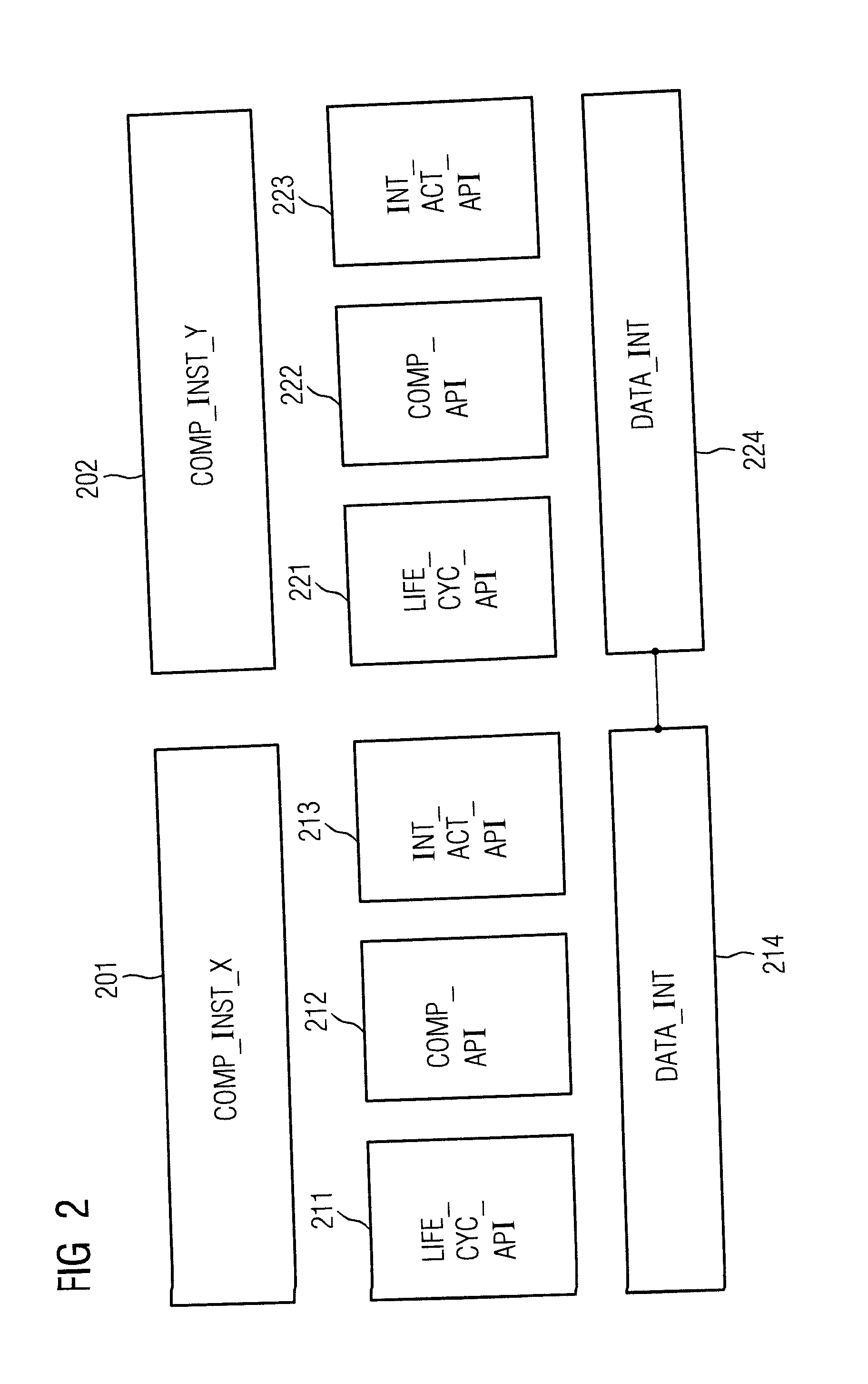
The present disclosure provides a method for flexibly and efficiently integrating functions distributed over multiple control units in an industrial automation system without requiring individual programming effort. The method uses an application programming interface to stipulate interactions between application components, allowing for real-time integration of loosely coupled services or functions at runtime. The interlinked component instances can be executed either within a control object or in isolation within separate subordinate control objects, improving system performance or component isolation, respectively.

Problems solved by technology

Firstly, it may be necessary to meet demands for realtime-compatible communication, having a comparatively large number of relatively short messages.
A weak communication infrastructure can compromise error-free provision of a service and have a disadvantageous effect on system stability and availability.
However, this reference does not deal with division of service components into service-specific and non-service-specific components.
However, this reference does not state that QoS measurements can be safeguarded by non-service-specific components.

Method used


Image

  • Method for providing functions within an industrial automation system, and industrial automation system
  • Method for providing functions within an industrial automation system, and industrial automation system
  • Method for providing functions within an industrial automation system, and industrial automation system

Examples


Embodiment Construction

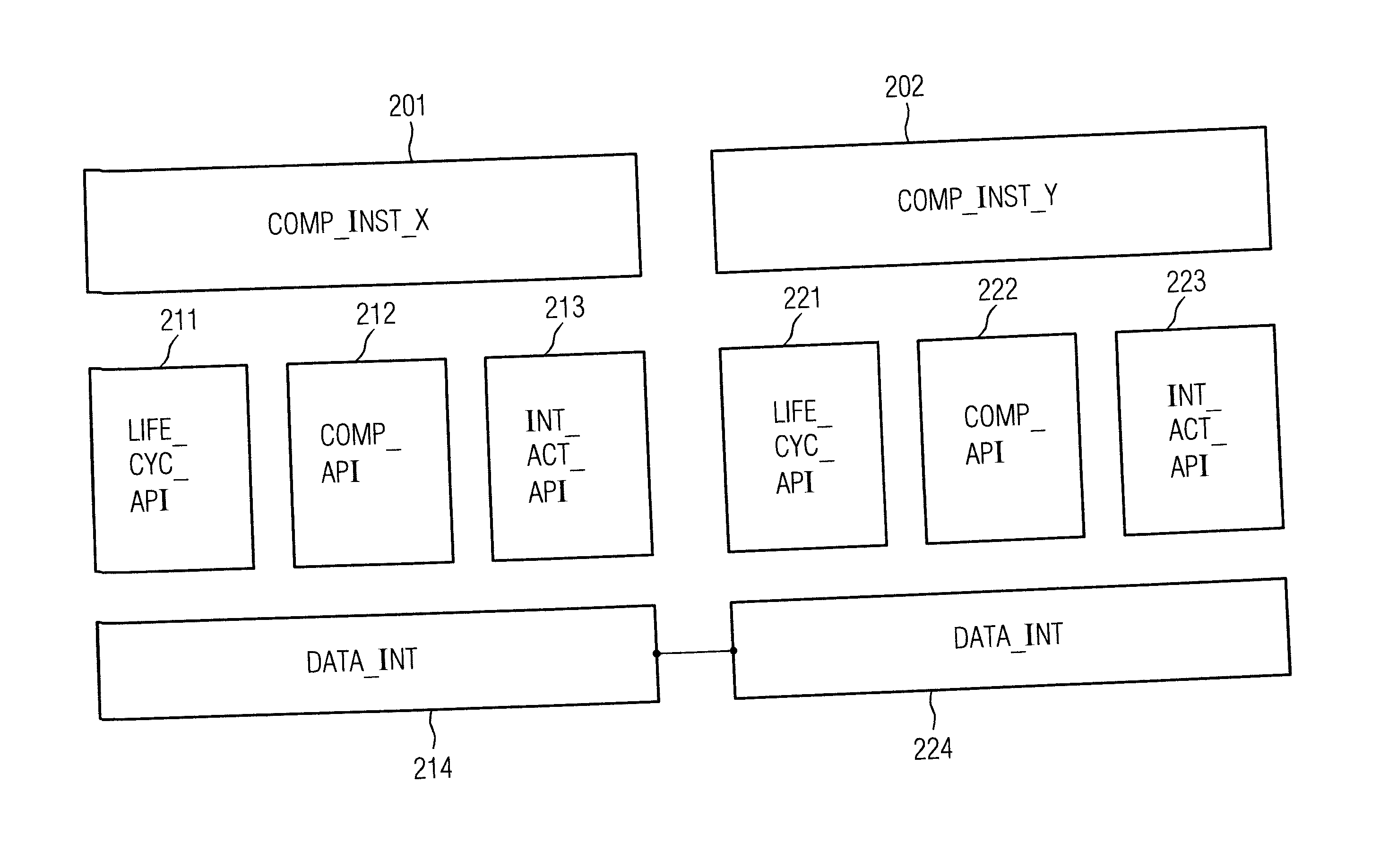
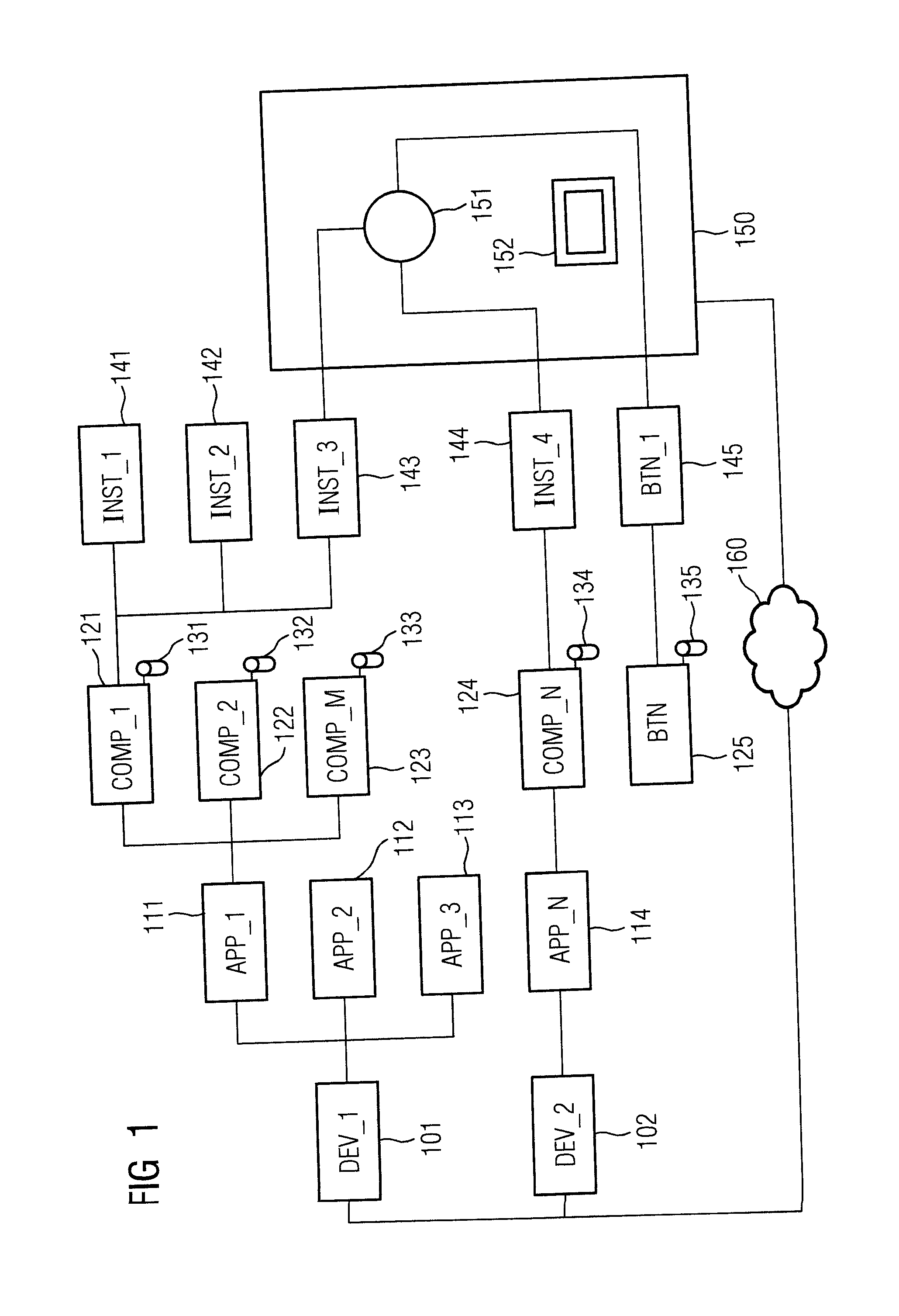
[0022]The industrial automation system shown in FIG. 1 comprises a plurality of control units 101-102 that respectively comprise at least one web server 111-114 configured to provide automation functions as web applications. The control units 101-102 are connected by a communication network 160 to at least one operator control and monitoring station 150 that has a web client 151 for linking web applications on the client at runtime on a user interface 152 on the client. In this exemplary embodiment, the user interface 152 on the client comprises a web browser.

[0023]The web applications each comprise at least one application component 121-125 that respectively have at least one component instance 141-145 produced for them at runtime. By way of example, these application components 121-125 may also include graphical user interface objects 125, such as buttons, provided by a standard application programming interface. Component instances 145 are also produced for such user interface ob...


PUM


Abstract

Method of providing functions within an industrial automation system and an industrial automation system thereof. Functions of the automation system are made available by web applications that are combined by the client during control program execution to form interlinked web applications. The functions are provided on a user interface of the client. The web applications are provided by a standard application programming interface that comprises a cross-component application programming interface for initializing and unloading application components and a component-specific application programming interface for event handling and providing component functions. Component instances are linked by an application programming interface for stipulating interactions between application components.

Description

BACKGROUND OF THE INVENTION[0001]Industrial automation systems are used for monitoring, controlling and regulating technical processes, particularly in the field of production, process, and buildings automation. Such systems allow operation of control devices, sensors, machines and industrial installations that are intended to operate as autonomously and independently of human interventions as possible. Due to the ever rising importance of information technology for automation systems (that comprise numerous networked control or computer units), methods for reliably providing functions distributed over an automation system for monitoring, control, and regulatory functions are becoming increasingly important.[0002]For distributed services, the service components that are provided by a plurality of different control or computer units for realizing functions of an automation system, impose great demands on a communication infrastructure of the automation system. Firstly, it may be nece...

Claims


Application Information

Patent Timeline
Patent Type & Authority Applications(United States)
IPC IPC(8): G05B15/02H04L29/08
CPCH04L67/02G05B15/02G05B19/0421G05B2219/25202G05B2219/25229G05B2219/25232H04L67/12H04L67/10G06F8/60H04L41/0836G06F9/445G06F9/46
Inventor ECKL, ROLANDHENRICH, ANDREASHERBERTH, HARALD
Owner SIEMENS AG
Learn More