Dual mode optical navigation device and mode switching method thereof

a navigation device and optical navigation technology, applied in the direction of mechanical pattern conversion, instruments, cathode-ray tube indicators, etc., can solve the problems of low accuracy of optical mouse, poor durability, and limited application of conventional optical mi

Inactive Publication Date: 2015-07-30
PIXART IMAGING INC
View PDF11 Cites 4 Cited by
  • Summary
  • Abstract
  • Description
  • Claims
  • Application Information

AI Technical Summary

Benefits of technology

[0008]The present disclosure provides a dual mode optical navigation device and a mode switching method thereof that may replace the function of the roller in conventional optical navigation devices so as to increase the practicality.
[0009]The present disclosure further provides a dual mode optical navigation device and a mode switching method thereof that may scroll windows smoothly according to a displacement of the navigation device relative to a working surface.
[0010]The present disclosure further provides a dual mode optical navigation device and a mode switching method thereof that may perform gesture operations according to a displacement of the navigation device relative to a working surface so as to enhance the user experience.
[0017]The dual mode optical navigation device according to the embodiment of the present disclosure may determine whether a first bottom surface or a second bottom surface contacts with a working surface according to an image feature of an image frame associated with the working surface or according to a detect signal of a gyroscope, an accelerometer or a switching element thereby switching the operation mode of the dual mode optical navigation device to control a cursor movement or perform a gesture operation. Accordingly, the problems existing in the conventional optical navigation device mentioned above may be overcome.

Problems solved by technology

Compared with the touch interface, conventional optical mice only have limited applications due to only being able to relatively control cursor movements according to the movement value.
However, using such additional elements to improve the user experience, the optical mouse can have problems of low accuracy, poor durability (e.g. due to abrasion of the roller) and large volume (e.g. due to ergonomic design of the pressing area of the buttons).

Method used


Image

  • Dual mode optical navigation device and mode switching method thereof
  • Dual mode optical navigation device and mode switching method thereof
  • Dual mode optical navigation device and mode switching method thereof

Examples


Embodiment Construction

[0026]It should be noted that, wherever possible, the same reference numbers will be used throughout the drawings to refer to the same or like parts.

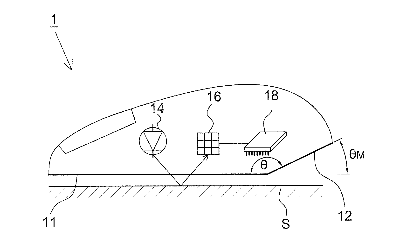
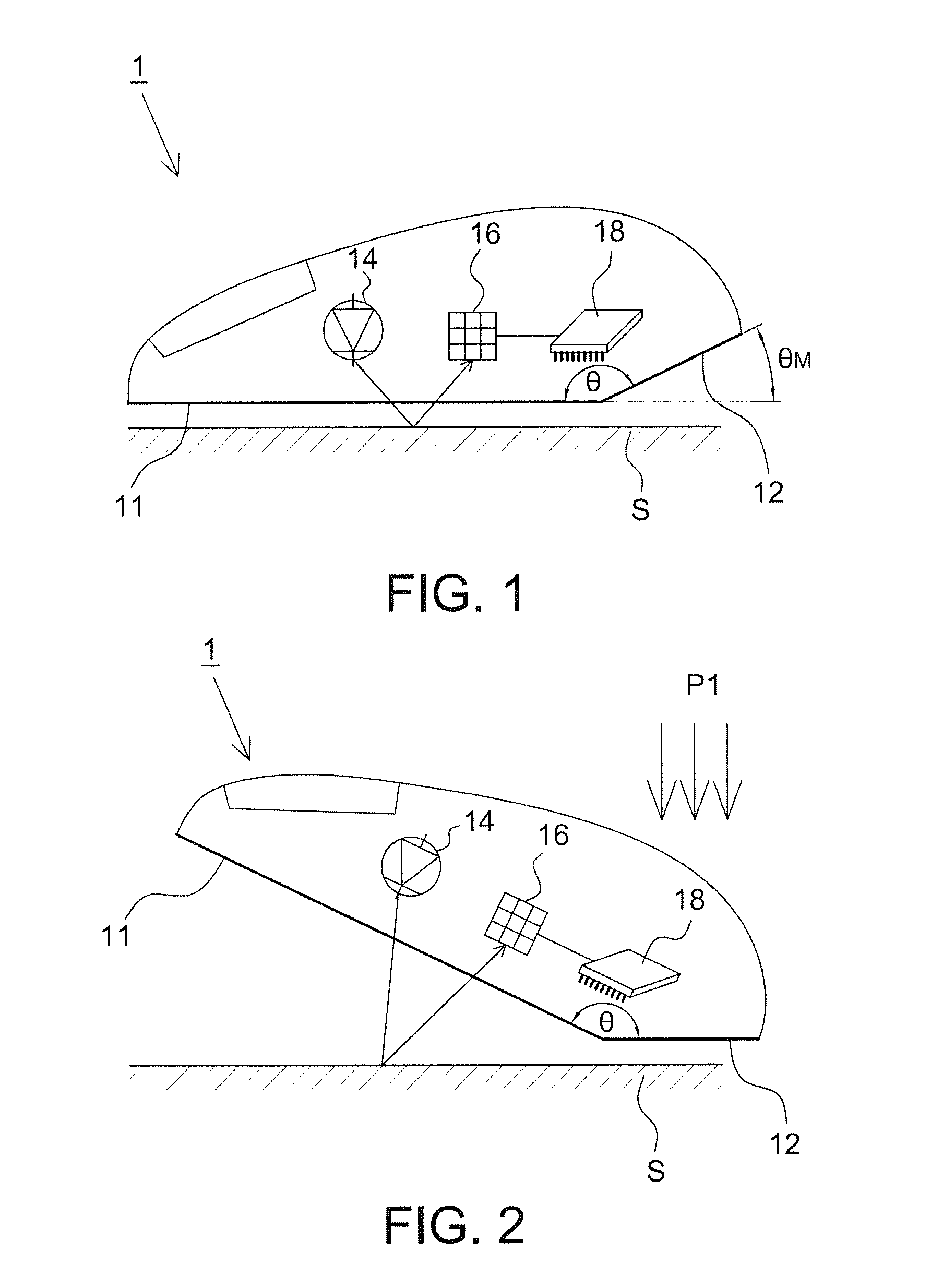
[0027]Referring to FIG. 1 and FIG. 2, FIG. 1 shows a schematic diagram of a dual mode optical navigation device 1 operating in a first mode according to the first embodiment of the present disclosure and FIG. 2 shows a schematic diagram of the dual mode optical navigation device 1 operating in a second mode according to the first embodiment of the present disclosure. The dual mode optical navigation device 1 includes a first bottom surface 11, a second bottom surface 12, a light source 14, an image sensor 16 and a process unit 18. The image sensor 16 is electrically connected to the process unit 18. A user (not shown) may operate the dual mode optical navigation device 1 on a working surface S in a first mode or a second mode with his / her palm or a plurality of fingers, wherein the first bottom surface 11 of the dual mode optical naviga...


PUM


Abstract

There is provided a mode switching method of a dual mode optical navigation device. The dual mode optical navigation device is configured to be operated on a working surface and has a first bottom surface and a second bottom surface having an included angle with the first bottom surface. The mode switching method includes: determining whether the first bottom surface or the second bottom surface contacts with the working surface; switching the dual mode optical navigation device to a first mode when identifying that the first bottom surface contacts with the working surface; and switching the dual mode optical navigation device to a second mode when identifying that the second bottom surface contacts with the working surface.

Description

BACKGROUND[0001]1. Field of the Disclosure[0002]This disclosure generally relates to an optical navigation device and, more particularly, to a dual mode optical navigation device and a mode switching method thereof that may switch the operation mode according to different operating states.[0003]2. Description of the Related Art[0004]The conventional optical navigation device, such as an optical mouse, generally includes a light source, an image sensor and a process unit. When a user operates the optical mouse on a working surface, the light source illuminates the working surface and the image sensor receives light reflected from the working surface. The process unit of the optical mouse calculates a movement value corresponding to the user's operation according to the images successively captured by the image sensor and converts the movement value to an electric signal. A host then relatively controls a cursor movement according to the electric signal.[0005]With the popularity of ge...

Claims


Application Information

Patent Timeline
Patent Type & Authority Applications(United States)
IPC IPC(8): G06F3/0354G06F3/01
CPCG06F3/017G06F3/03543G06F3/0338G06F3/0346G06F3/0362G06F3/0304
Inventor LEE, SAI-MUN
Owner PIXART IMAGING INC
Why Eureka
Try Eureka