System and control method
- Summary
- Abstract
- Description
- Claims
- Application Information
AI Technical Summary
Benefits of technology
Problems solved by technology
Method used
Image

Examples
first embodiment
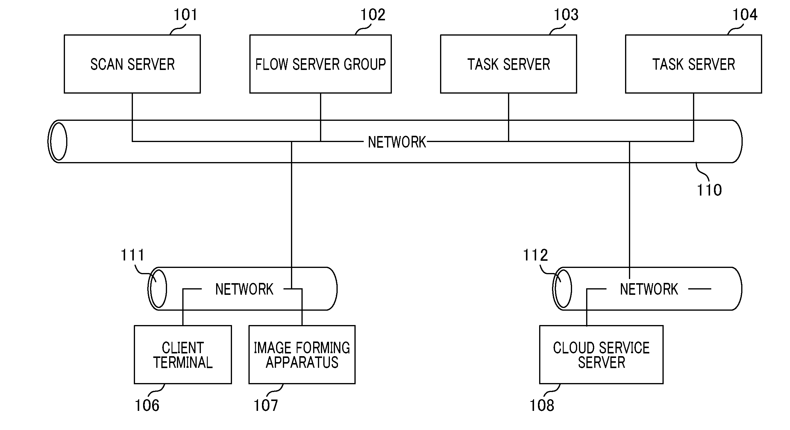
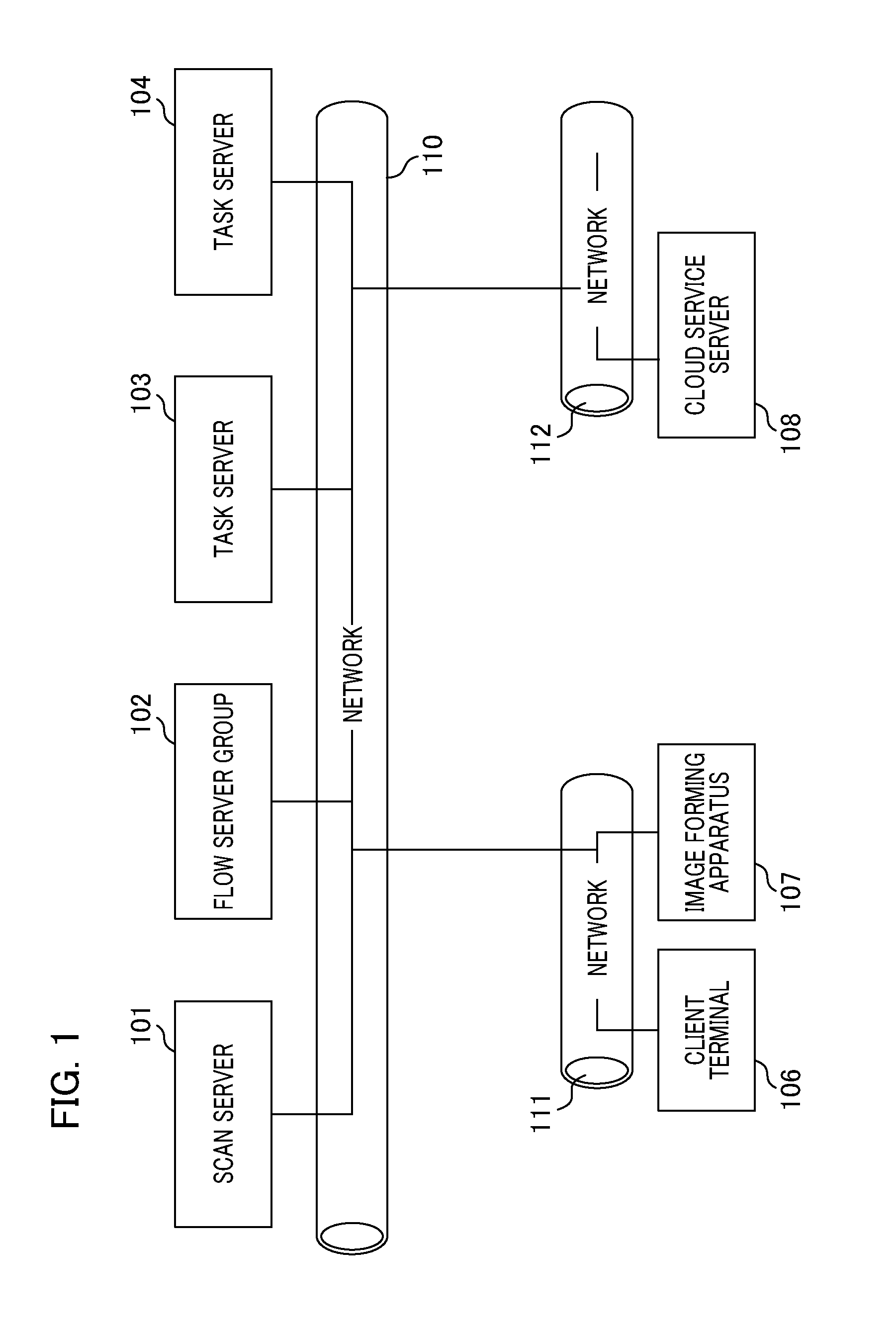
[0041]FIG. 1 illustrates a configuration of an overall information processing system according to an embodiment of the present invention. The information processing system of the present embodiment is a cloud system that provides an image processing service to a user of a client terminal 106. The information processing system in FIG. 1 comprises a scan server 101, a flow server group 102, task servers 103 and 104, the client terminal 106, an image forming apparatus 107, and a cloud service server 108.
[0042]The configuration as shown in FIG. 1 is intended to be an example, and it is assumed that a plural number of each of the task servers 103 and 104, the client terminal 106, the image forming apparatus 107, and the cloud service server 108 that are connected to a network. From the scan server 101 to the task server 104, there is a communicable connection via a network 110. The client terminal 106 and the image forming apparatus 107 are communicably connected from the scan server 101...
second embodiment
[0088]In the first embodiment, a case is supposed in which a large number of file saving requests are executed from the scan server 101 or the task servers 103 and 104 to the file saving unit 1511. At this time, a large number of the priority acquisition requests are generated to the saving address server priority determining unit 1522. Specifically, access is concentrated on the file management server managing DB for managing a startup state and a non-startup state in each apparatus. Therefore, the load on the database is increased, and the performance of the server is reduced.
[0089]When via the file saving unit 1511, the file save processing unit 1521 receives the file saving request from the scan server 101 or the task servers 103 and 104, a difference between the second embodiment and the first embodiment is the method for determining the priority of the saving address server priority determining unit 1522. In the second embodiment, a description will be given of a method for de...
third embodiment
[0097]In the second embodiment, a case is supposed in which only a connection between a certain file management service server and another file management service server is not possible. For example, the case comprises a case as shown in FIG. 16A. FIG. 16A illustrates a situation in which file management service servers L1701 to N1703 are operating. This situation illustrates an example in which a setting of the firewall is wrong, which causes a disconnection between the file management service server L1701 and a file management service server M1702. Specifically, in FIG. 16A, marks o and marks x respectively illustrate whether a connection between the file management service servers in the direction of arrows can be executed or not.
[0098]FIG. 16C illustrates a state of the file management server managing DB unit 1532 shown in FIG. 16A, and a state that all servers are operated. In this state, if the processing is executed according to the processing if the processing fails as descr...
PUM
 Abstract
Description
Claims
Application Information
 - R&D
- Intellectual Property
- Life Sciences
- Materials
- Tech Scout
- Unparalleled Data Quality
- Higher Quality Content
- 60% Fewer Hallucinations
Browse by: Latest US Patents, China's latest patents, Technical Efficacy Thesaurus, Application Domain, Technology Topic, Popular Technical Reports.
© 2025 PatSnap. All rights reserved.Legal|Privacy policy|Modern Slavery Act Transparency Statement|Sitemap|About US| Contact US: help@patsnap.com