Electrosurgical system

a surgical system and electro-optical technology, applied in the field of electro-optical systems, can solve problems such as tissue cutting capability

Active Publication Date: 2015-08-06
GYRUS MEDICAL LTD
View PDF4 Cites 6 Cited by
  • Summary
  • Abstract
  • Description
  • Claims
  • Application Information

AI Technical Summary

Benefits of technology

[0004]Embodiments of the invention provide an instrument which is more versatile than any of the instruments in the prior art, and in particular provides for selecting between non-contact tissue coagulation and non-contact tissue removal. Accordingly, an electrosurgical system is provided for the treatment of tissue, the system comprising an electrosurgical instrument, a source for supplying ionisable gas to said electrosurgical instrument, an electrosurgical generator for supplying high frequency energy to said electrosurgical instrument, and a switch mechanism, the electrosurgical instrument including at least one elongated shaft having a proximal end and a distal end, and including at least one conduit though which ionisable gas can be supplied to the distal end of the shaft, the shaft including at least one aperture located at the distal end thereof, and at least one electrode for ionising the ionisable gas exiting the at least one aperture, the electrosurgical instrument being movable between at least a first and a second arrangement, the first arrangement being such that the at least one electrode produces a stream of ionised gas exiting the at least one aperture of such energy that it is capable of the removal of the tissue being treated, and the second arrangement being such that the at least one electrode produces a stream of ionised gas exiting the at least one aperture capable of the coagulation of the tissue being treated, the operation of the switch mechanism causing the electrosurgical instrument to switch between the first and second arrangements.

Problems solved by technology

However, U.S. Pat. No. 5,669,907 provides only tissue coagulation and has no tissue-cutting capability whatsoever.

Method used


Image

  • Electrosurgical system
  • Electrosurgical system
  • Electrosurgical system

Examples


Embodiment Construction

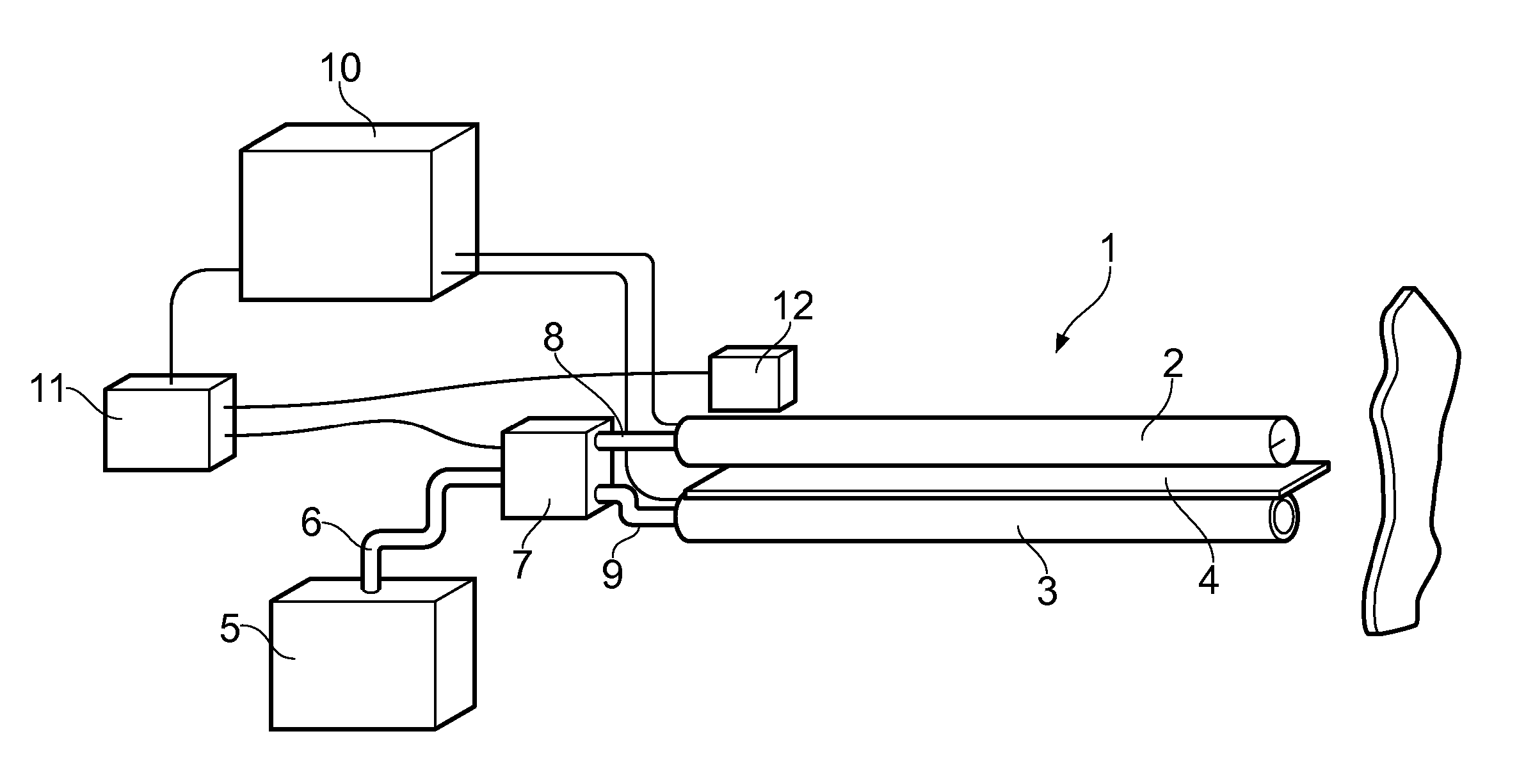
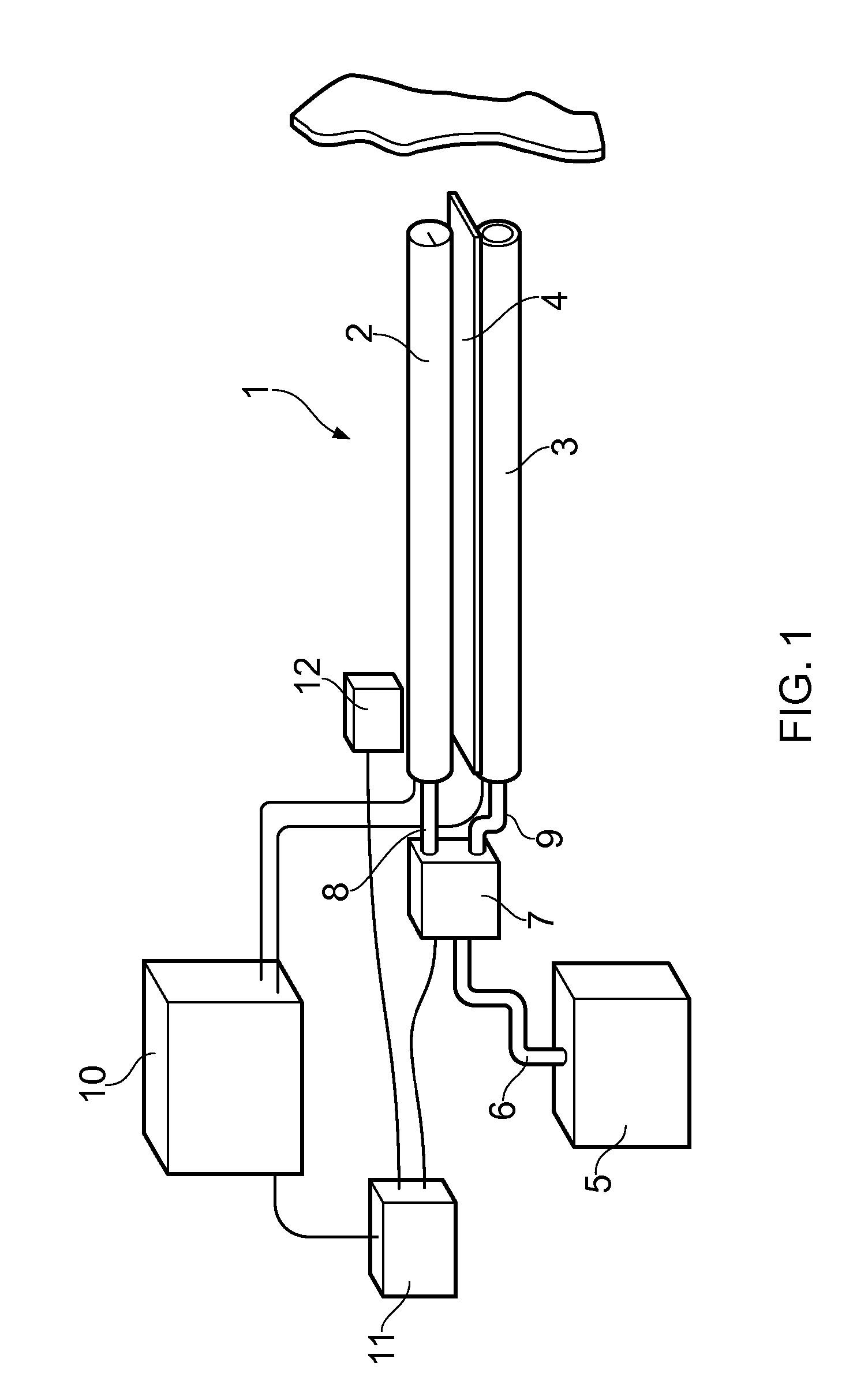
[0027]Referring to FIG. 1, an electrosurgical system comprises an instrument shown generally at 1, consisting of a first tube 2 and a second tube 3, situated parallel to one another and separated by a ceramic divider 4. Argon gas is supplied to each tube from a reservoir 5, via a pipe 6 and a flow valve 7. The flow valve directs the argon gas to one or both of tubes 2&3, via pipes 8&9. An electrosurgical generator 10 provides RF energy to electrodes mounted on each tube, to be described in more detail later. A switch mechanism 11 send signals to control the electrosurgical generator 10 and also the flow valve 7, as well as a servo motor 12 the function of which will also be described in more detail later.

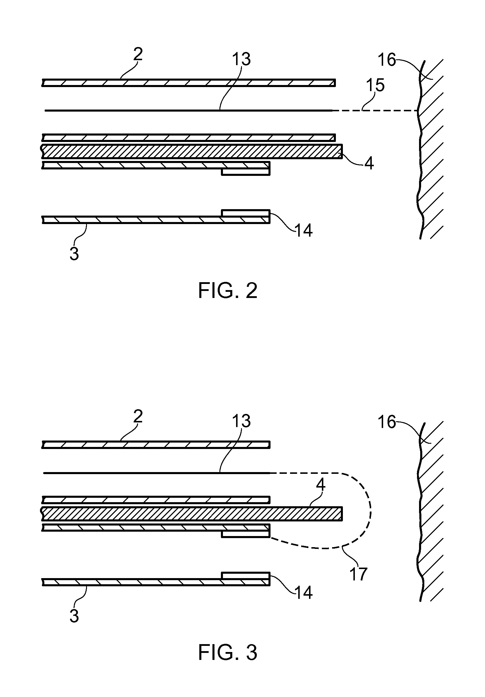
[0028]FIG. 2 shows the distal end of the tubes 2&3 in a first arrangement suitable for tissue removal. The servo motor has moved the first tube 2 forwardly, so that it is in advance of the second tube 3. A central tungsten electrode 13 is provided coaxially within the first tube 2, ...


PUM


Abstract

An electrosurgical system for the treatment of tissue includes an electrosurgical instrument, a source for supplying ionisable gas to said electrosurgical instrument, an electrosurgical generator for supplying high frequency energy to the electrosurgical instrument, and a switch mechanism. The electrosurgical instrument includes one or more conduits and one or more electrodes connected to the electrosurgical generator. The electrosurgical system is movable between at least a first and a second arrangement. The first arrangement is such that one electrode produces a stream of ionised gas exiting one of the conduits, the ionisable gas being capable of the removal of tissue. The second arrangement is such that ionised gas is produced such that it is capable of the coagulation of tissue. The switch mechanism causes the electrosurgical instrument to move between the first and second arrangements.

Description

TECHNICAL FIELD[0001]This invention relates to an electrosurgical system and in particular to the non-contact treatment of tissue using an ionisable gas such as argon.BACKGROUND TO THE INVENTION[0002]Argon beam coagulators have been known for many years, and examples are given in U.S. Pat. Nos. 4,040,426, 6,039,736 and 6,197,026. The first example is an end-effect instrument, in which the ionised gas exits through the end of the instrument, while the latter two examples are directed at side-effect instruments, in which the ionised gas exits the instrument though an aperture in the side of the instrument. Such instruments are often referred to as APC instruments (Argon Plasma Coagulation).[0003]The majority of these instruments perform purely tissue coagulation and have no tissue cutting capability. Where such instruments do have a tissue cutting capability, this is achieved by a tissue contacting needle or other electrode. Examples are U.S. Pat. Nos. 5,088,997 and 6,702,812, which b...

Claims


Application Information

Patent Timeline
Patent Type & Authority Applications(United States)
IPC IPC(8): A61B18/04
CPCA61B18/042A61B2018/00166A61B2018/1475A61B2018/00601A61B2018/00958A61B2018/00589
Inventor NAGTEGAAL, MARNOWILLIAMS, WAYNETAYLOR, ROBERT EDWARD
Owner GYRUS MEDICAL LTD
Why Eureka
Try Eureka