Device for Automated Capsulotomy

a capsulotomy and automated technology, applied in the field of capsulotomy devices and methods, can solve the problems of weakening the capsule, difficult to create the required level of precision in the lens capsule, and capsules may not be able to hold, so as to achieve the effect of higher electrical resistan

a capsulotomy and automated technology, applied in the field of capsulotomy devices and methods, can solve the problems of weakening the capsule, difficult to create the required level of precision in the lens capsule, and capsules may not be able to hold, so as to achieve the effect of higher electrical resistan

US20150216727A1Active Publication Date: 2015-08-06MYNOSYS CELLULAR DEVICES INC

Image

  • Device for Automated Capsulotomy
  • Device for Automated Capsulotomy
  • Device for Automated Capsulotomy

Examples


Embodiment Construction

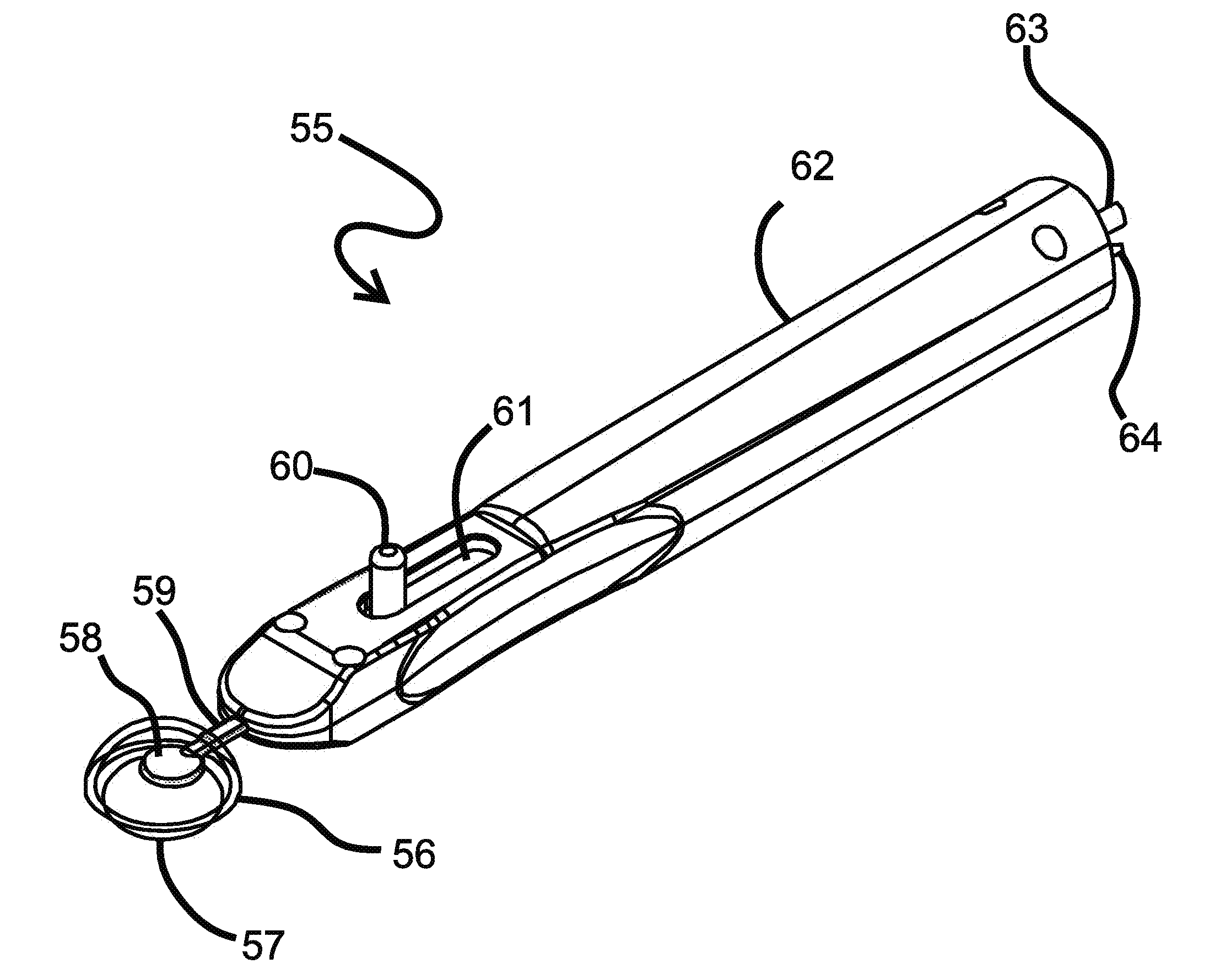
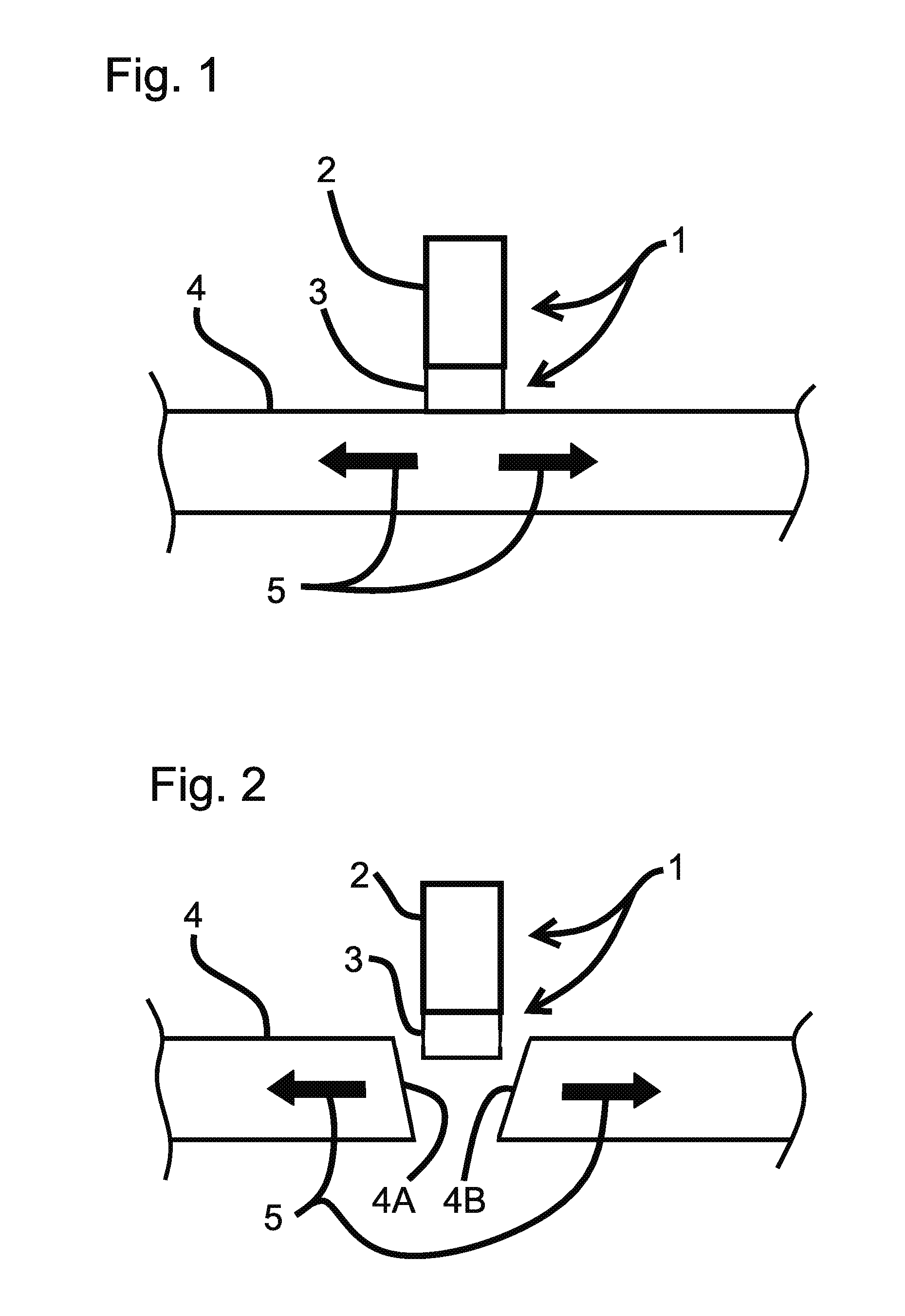
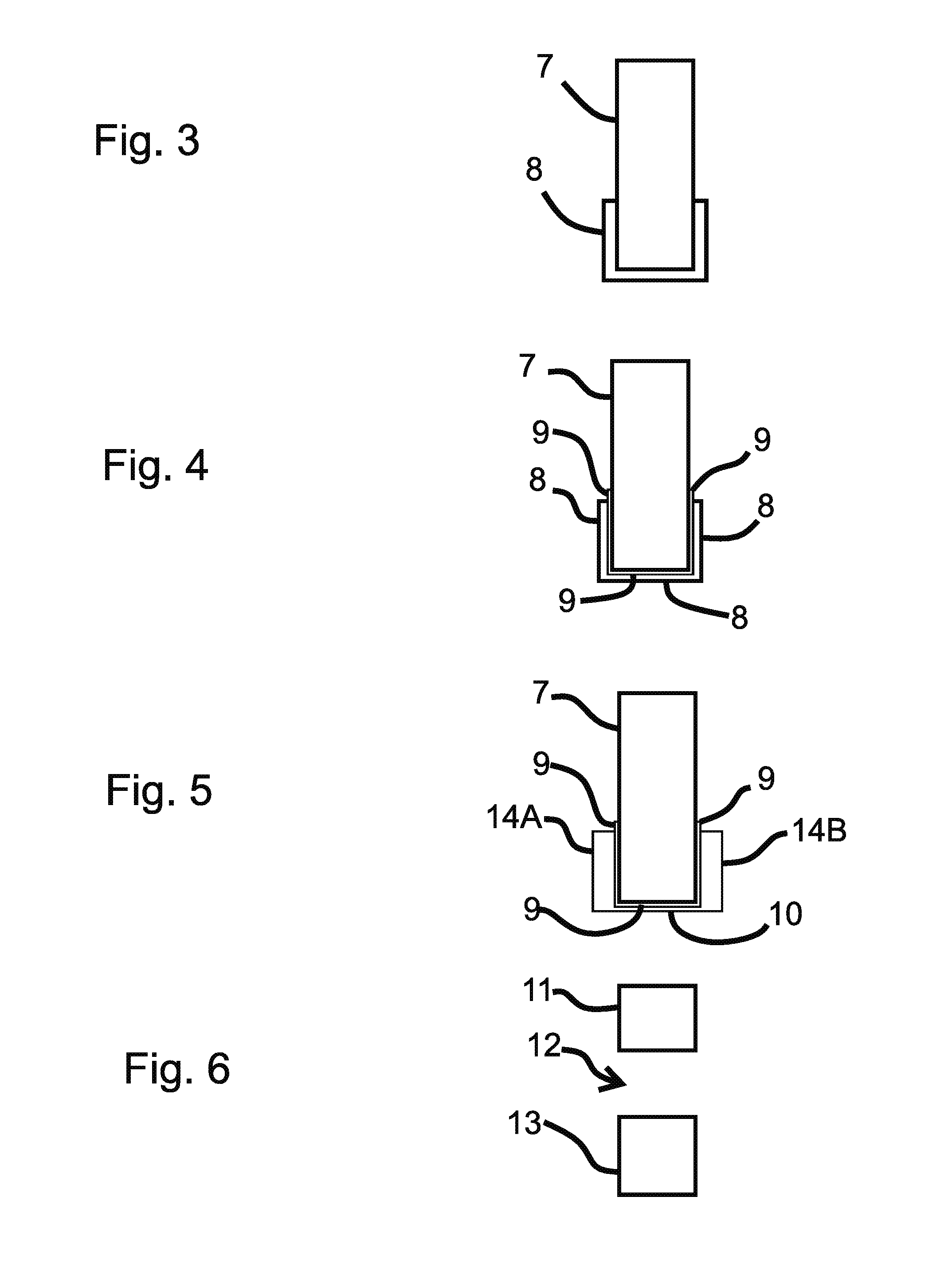
[0082]The figures and the following description relate to various embodiments of the invention by way of illustration only. It should be noted that from the following discussion, alternative embodiments of the structures and methods disclosed herein will be readily recognized as viable alternatives that may be employed without departing from the principles of what is claimed.

[0083]Reference will now be made in detail to several embodiments, examples of which are illustrated in the accompanying figures. It is noted that wherever practicable similar or like reference numbers may be used in the figures and may indicate similar or like functionality. The figures depict embodiments of the disclosed system (or method) for purposes of illustration only. One skilled in the art will readily recognize from the following description that alternative embodiments of the structures and methods illustrated herein may be employed without departing from the principles described herein.

[0084]Embodime...


PUM

PropertyMeasurementUnit
thicknessaaaaaaaaaa
thicknessaaaaaaaaaa
thickaaaaaaaaaa

Abstract

A surgical device is disclosed for cutting tissue, including for performing a capsulotomy of a lens capsule of an eye. This device includes a reversibly collapsible cutting element for cutting a portion of a capsule membrane of the eye. The cutting element includes an outer layer, an inner layer, and a bottom layer that has a higher electrical resistance than the electrical resistance of the outer layer and the inner layer. The bottom layer is configured to conduct an electrical current between the outer layer and the inner layer, which causes a temperature increase in the bottom layer for cutting tissue.

Description

CROSS-REFERENCE TO RELATED APPLICATIONS[0001]This application claims the benefit of U.S. Provisional Application No. 61 / 703,514, filed Sep. 20, 2012, the disclosure of which is incorporated herein by reference.GOVERNMENT RIGHTS[0002]This invention was made with government support under the Small Business Innovation Research Program (Contract No. 1R43EY021023-01A1), awarded by the National Institutes of Health. The government has certain rights in the invention.BACKGROUND[0003]1. Technical Field[0004]This disclosure relates to devices and methods for performing a capsulotomy, and more specifically, devices and methods for using an electrical cutting element to cut a membrane of the eye during a capsulotomy.[0005]2. Description of the Related Art[0006]Lens cataract is the leading cause of blindness worldwide and surgical treatment by cataract removal is the treatment of choice. If the lens of an eye develops opaque areas, as in a cataract, the lens must be surgically removed. The lens...

Claims


Application Information

Patent Timeline
06 Aug 2015
Publication
US20150216727A1
IPC
A61F9/007; A61B18/08
CPC
A61F9/00754; A61B2018/00601; A61B18/082; A61F9/0079; A61B2018/00107; A61B2018/00321
Inventors
KELLER, CHRISTOPHER GUILD