Subframe For a Motor Vehicle, In Particular a Front Axle Subframe, and Bodywork Comprising such a Subframe

a subframe and motor vehicle technology, applied in the direction of vehicle components, understructures, transportation and packaging, etc., can solve the problems of component failure, risk of bodywork floating, etc., and achieve the effect of high security and easy mounting

Active Publication Date: 2015-08-06
AUTOTECH ENG DEUT
View PDF15 Cites 13 Cited by
  • Summary
  • Abstract
  • Description
  • Claims
  • Application Information

AI Technical Summary

Benefits of technology

[0009]The problem addressed by the present invention is that of providing a subframe of the type mentioned at the

Problems solved by technology

In this context, in particular in the case of powerful vehicles and electric-motor-driven vehicles, which have high torques owing to the regenerative braking th

Method used


Image

  • Subframe For a Motor Vehicle, In Particular a Front Axle Subframe, and Bodywork Comprising such a Subframe
  • Subframe For a Motor Vehicle, In Particular a Front Axle Subframe, and Bodywork Comprising such a Subframe
  • Subframe For a Motor Vehicle, In Particular a Front Axle Subframe, and Bodywork Comprising such a Subframe

Examples


Embodiment Construction

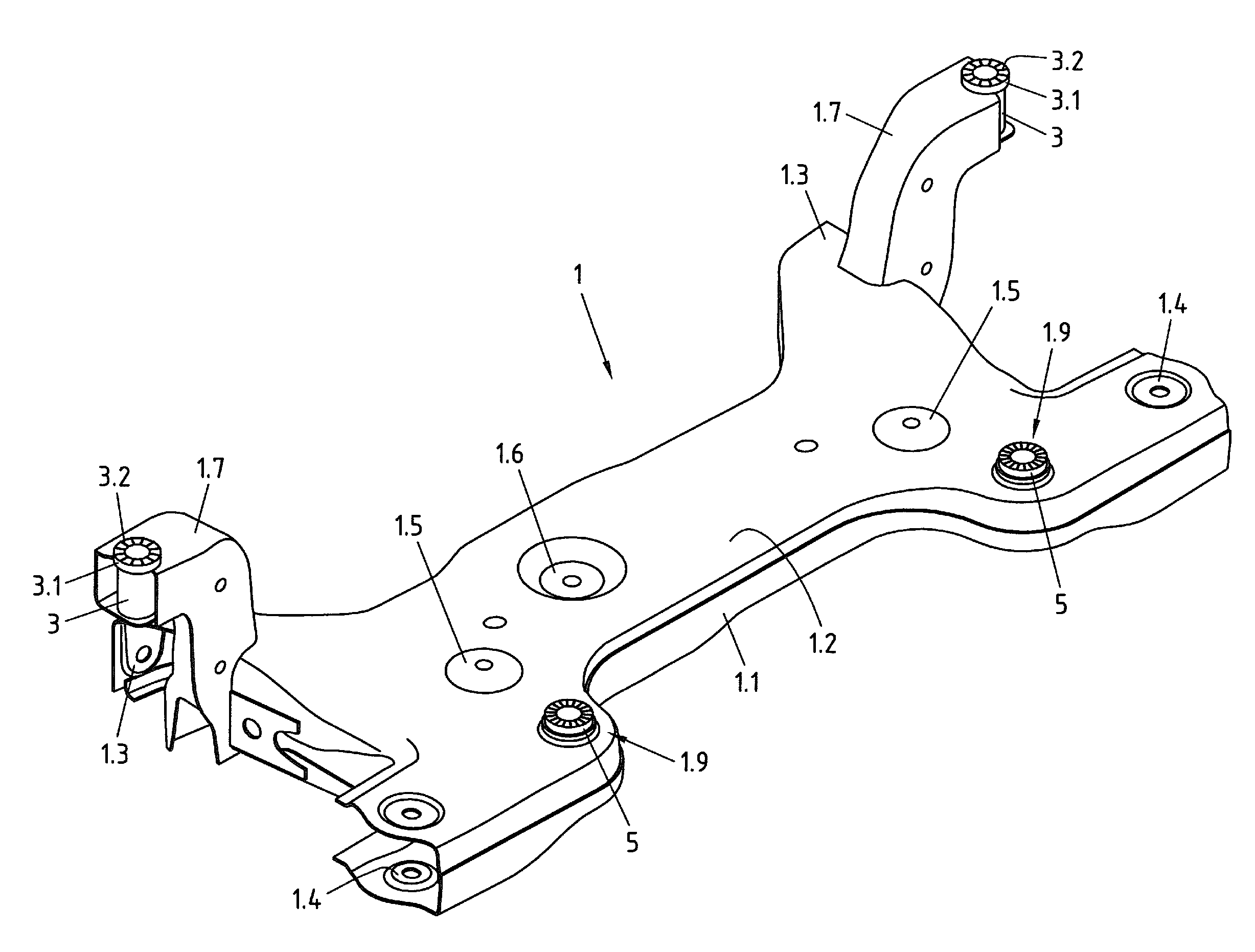
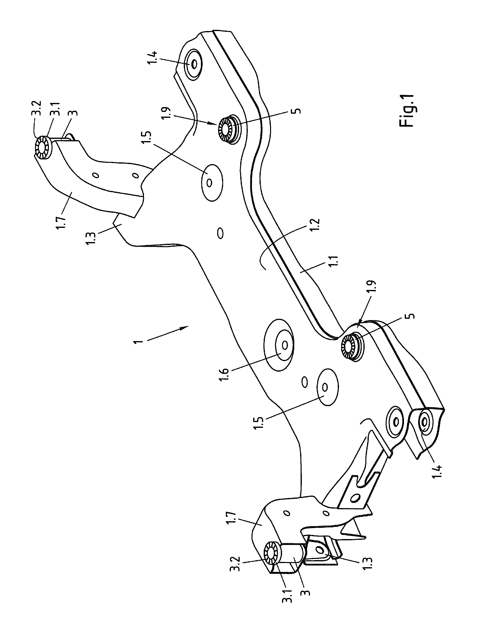
[0027]The shaped part 1 shown in FIG. 1 is a front axle subframe for a motor vehicle. The subframe 1 is constructed in a shell design. It is composed of a first shell element 1.1 and a second shell element 1.2 which are welded to each other and define a cavity 2. In the embodiment shown, the first shell element 1.1 may also be referred to as the lower shell and the second shell element 1.2 may also be referred to as the upper shell. The edges of the lower shell 1.1 and the upper shell 1.2 are joined to one another with a lap joint, for example.

[0028]Connection points 1.3, 1.4 for receiving bodywork-side bearing elements (for example rubber bearing bushes) of a left-hand and a right-hand transverse link (not shown) of a wheel suspension are formed on the transverse sides of the subframe 1. Furthermore, the upper shell 1.2 comprises base-shaped embossed portions 1.5, which are provided with fastening means or screw holes for rigidly connecting a steering gear housing (not shown). Furt...


PUM


Abstract

The invention relates to a subframe for a motor vehicle, in particular a front axle subframe, including a first shell element and a second shell element which is rigidly connected to the first shell element and defines a cavity therewith, and at least one bodywork connection sleeve for inserting a screw therethrough. The bodywork connection sleeve is attached at one of its ends to a through-hole in the first shell element and extends within the cavity towards a through-hole in the second shell element. So that such a subframe can be easily mounted and can provide a high level of security against slipping relative to the bodywork, the invention provides that an annular disc is allocated to the attached end of the bodywork connection sleeve, which disc projects radially relative to the outer surface of the sleeve, is arranged on the outside of the first shell element and is integrally bonded thereto, and that a toothed disc produced separately from the bodywork connection sleeve is arranged on the outside on the through-hole in the second shell element, which the other end of the bodywork connection sleeve faces, which toothed disc has an external diameter which is greater than the internal diameter of the through-hole in the second shell element, and is integrally bonded to the second shell element.

Description

CROSS-REFERENCE TO RELATED APPLICATION[0001]This application claims priority to European Patent Application No. 14153651.6 filed Feb. 3, 2014, the disclosure of which is hereby incorporated in its entirety by reference.BACKGROUND OF THE INVENTION[0002]1. Field of the Invention[0003]The invention relates to a subframe for a motor vehicle, in particular a front axle subframe, comprising a first shell element and a second shell element which is rigidly connected to the first shell element and defines a cavity therewith, and comprising at least one bodywork connection sleeve for inserting a screw therethrough, the bodywork connection sleeve being attached at one of its ends to a through-hole in the first shell element and extending within the cavity towards a through-hole in the second shell element.[0004]The invention further relates to bodywork for a motor vehicle comprising such a subframe.[0005]2. Description of Related Art[0006]Known front axle subframes for motor vehicles are comp...

Claims


Application Information

Patent Timeline
IPC IPC(8): B62D21/11
CPCB62D21/11
Inventor HASELHORST, KAIFRIESEN, VIKTOR
Owner AUTOTECH ENG DEUT
Why Eureka
Try Eureka