
Control surface actuation assembly

Inactive Publication Date: 2015-08-06
MOOG WOLVERHAMPTON
View PDF10 Cites 12 Cited by
  • Summary
  • Abstract
  • Description
  • Claims
  • Application Information

AI Technical Summary

Benefits of technology

The present invention provides a solution to prevent problem with the actuator in the load path between the wing and aileron, which could lead to the control surface entering the flutter mode. A dedicated, separate single damper is introduced as a measure against this issue, which is simpler and lighter than an additional actuator assembly and reduces cost and complexity. Additionally, a gearbox is provided to drive the output arm, where at least one gear of the gearbox is earthened to the housing, which improves the overall stiffness of the housing and allows for material savings.

Problems solved by technology

Normally, this would be unacceptable because any problem with the actuator would result in the control surface entering the flutter mode.

Method used


Image

  • Control surface actuation assembly
  • Control surface actuation assembly
  • Control surface actuation assembly

Examples


Embodiment Construction

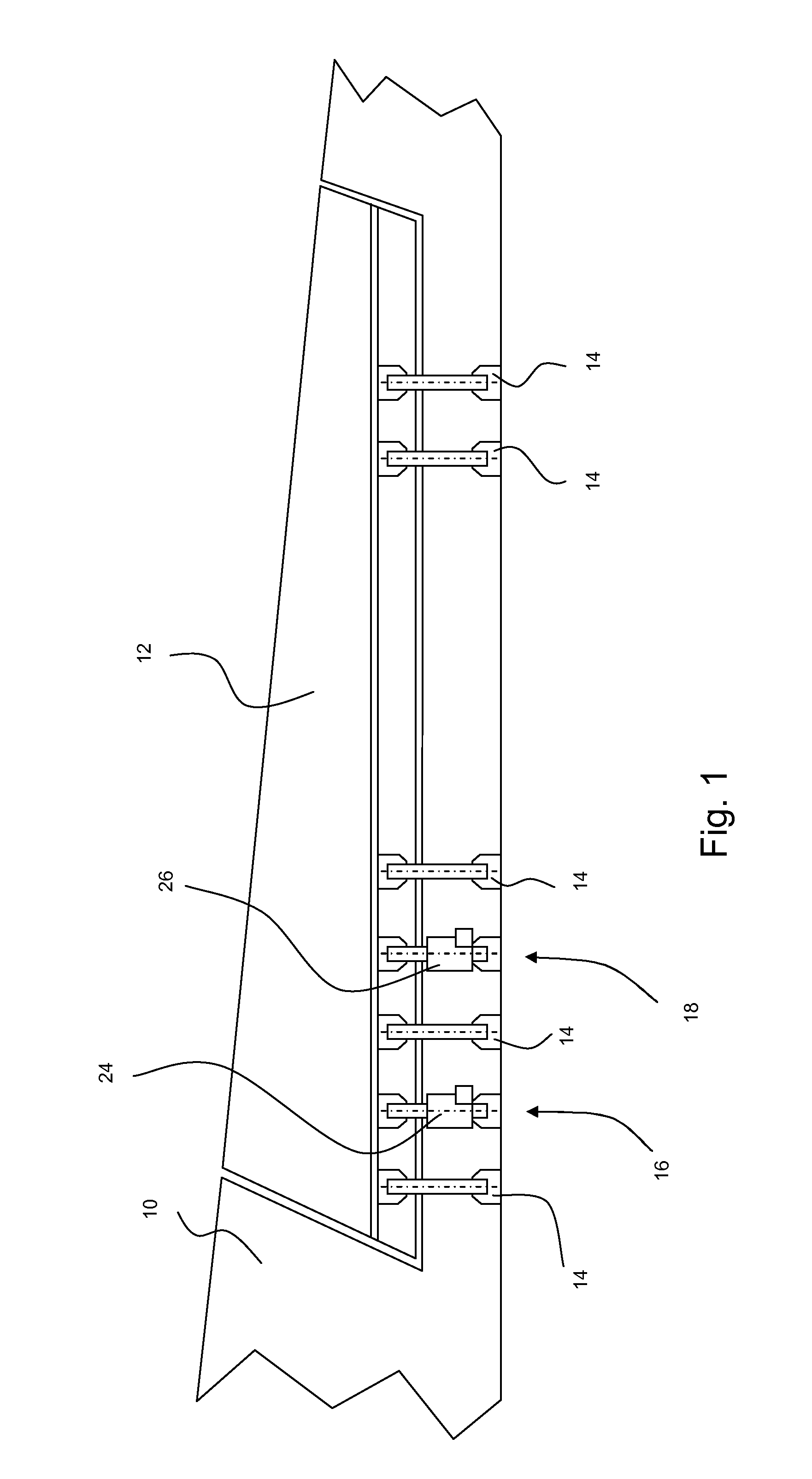
[0064]Turning to FIG. 1, a part of an aircraft wing 10 is shown to which an aileron panel 12 is movably mounted. The aileron panel 12 is attached to the wing 10 via five mechanical link assemblies 14, being spaced apart and configured to allow articulation of the aileron 12 through a predetermined range of motion, to control the aerodynamic properties of the wing in flight.

[0065]A first hydraulic servo-actuator 16 and a second hydraulic servo-actuator 18 are provided and are configured to move the aileron panel 12 relative to the wing 10. Each servo-actuator 16, 18 is powered by a respective hydraulic ram 24, 26, each of which is fed by a separate and independent hydraulic supply (not shown).

[0066]In use, the hydraulic servo-actuators 16, 18 are in an active / standby control mode. In other words, the first hydraulic servo-actuator 16 powers the aileron panel 12 for movement in response to commands from the flight control computer. During such actuation, the second hydraulic servo-act...


PUM


Abstract

An aircraft control surface actuation assembly comprises a first electromechanical actuator assembly (44) driven by two independent motors (48, 50) for redundancy, with a damping assembly (46) provided to mitigate flutter.

Description

CROSS-REFERENCE TO RELATED APPLICATIONS[0001]The present application is the U.S. national phase of International Application No. PCT / GB2013 / 052144 filed Aug. 12, 2013, which claims priority of British Application No. 1214952.2 filed Aug. 22, 2012, the entirety of which is incorporated herein by reference.FIELD OF THE INVENTION[0002]The present invention is concerned with an aircraft control surface actuation assembly. More specifically, the present invention is concerned with an electrically powered actuation assembly for the actuation of primary aircraft control surfaces, in particular ailerons.BACKGROUND OF THE INVENTION[0003]Many aircraft use hydraulically powered control surface actuation assemblies to move the primary control surfaces such as ailerons. Two linear hydraulic servo-actuators per aileron surface are often provided (for example on the Airbus A320™. Each linear hydraulic servo-actuator comprises a separate hydraulic ram to move the aileron surface. The motion of each...

Claims


Application Information

Patent Timeline
IPC IPC(8): B64C13/50G01M17/04B64C13/34
CPCB64C13/503Y02T50/44B64C13/34F16H2001/2881G01M17/04F16H1/46F16H2001/2872B64C13/50B64C13/505Y02T50/40
Inventor DAVIES, JONATHAN
Owner MOOG WOLVERHAMPTON
Learn More