Radar antenna

Active Publication Date: 2015-08-06
FURUNO ELECTRIC CO LTD
View PDF0 Cites 3 Cited by
  • Summary
  • Abstract
  • Description
  • Claims
  • Application Information

AI Technical Summary

Benefits of technology

The patent describes a radar antenna that can show detection results without a wired connection. It is designed to be easy to install and can be positioned anywhere. The wireless LAN antenna is fixed to the radar case and can communicate with external devices at a stable distance. This enables stable communication without interruption from other parts of the radar antenna. Overall, the radar antenna provides efficient and flexible detection without the need for wires.

Problems solved by technology

Particularly, since radar antennas are normally disposed at a high position, a wireless LAN radio wave is difficult to be interrupted by an obstacle or the like, and therefore, the radio wave can efficiently be transmitted.

Method used


Image

  • Radar antenna
  • Radar antenna
  • Radar antenna

Examples


Embodiment Construction

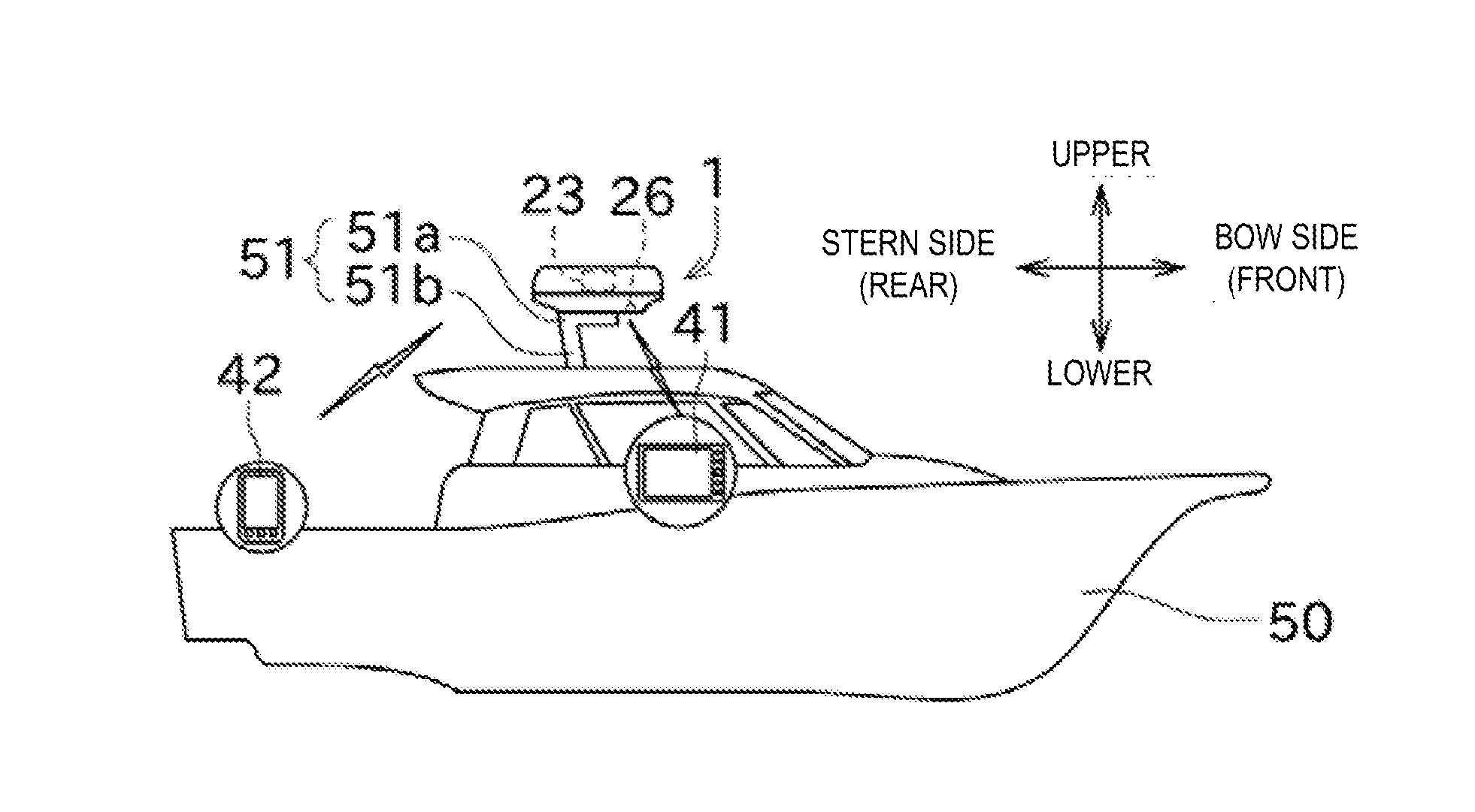
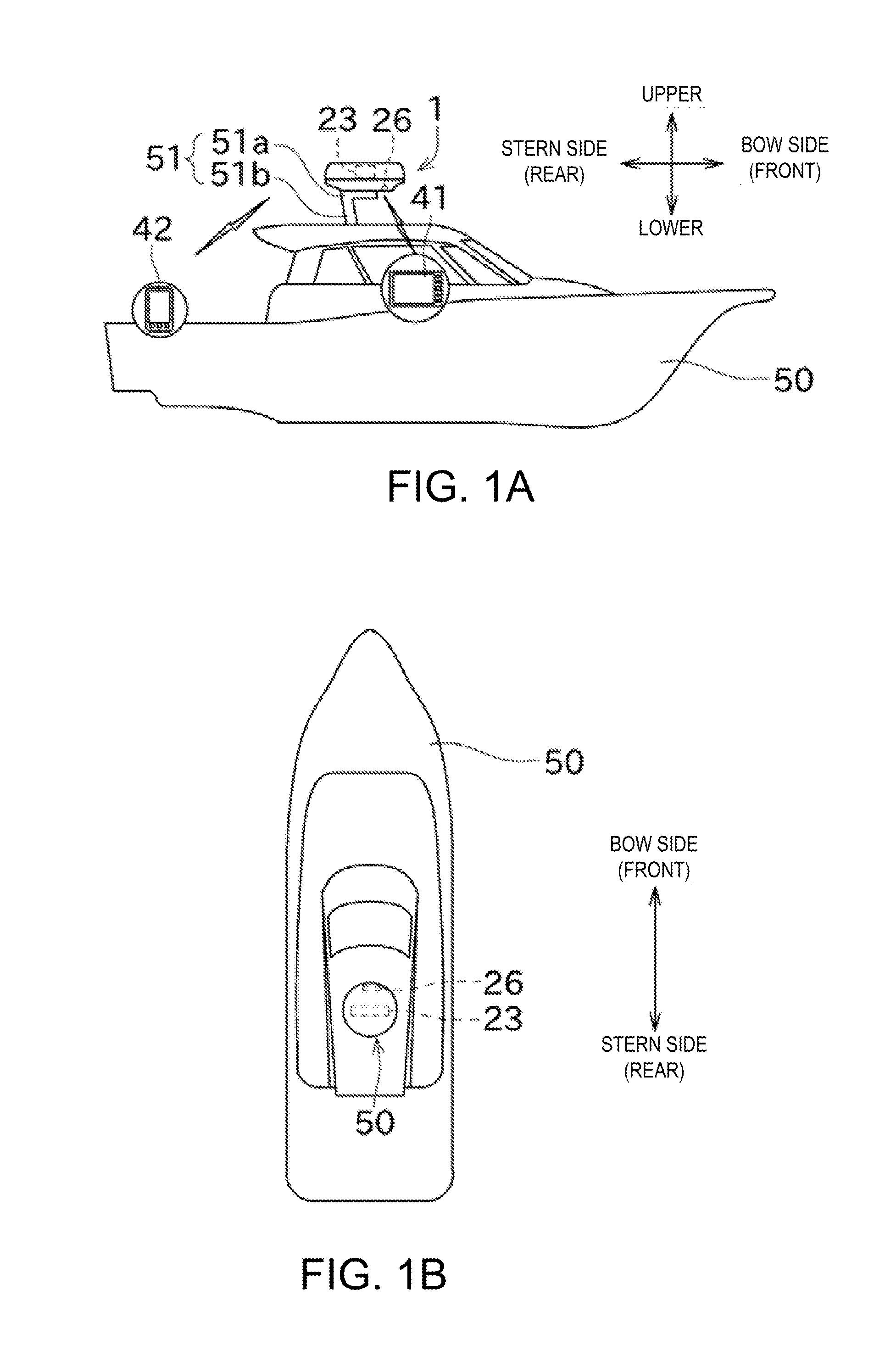
[0024]Next, one embodiment of this disclosure is described with reference to the appended drawings. First, a radar antenna 1 of this embodiment is schematically described with reference to FIGS. 1A and 1B. The radar antenna 1 is installed in a movable body, and in this embodiment, the movable body is a ship 50. Specifically, a pedestal 51 is provided, for example, either one of above a cabin and on a mast of the ship 50, etc. The pedestal 51 includes a mount part 51a and a supporting column 51b. The radar antenna 1 is attached to the mount part 51a. The supporting column 51b extends in a lower direction of the ship from a rear position of the mount part 51a and supports the mount part 51a.

[0025]The radar antenna 1 transmits transmission signals (radio waves) outside and receives, as reception signals, reflection waves caused by the transmission signals reflecting on target object(s), etc. The radar antenna 1 analyzes each reception signal and detects position(s) of the target objec...


PUM


Abstract

A radar antenna is provided. The radar antenna includes a radar case having a front side and a rear side, a signal processor provided inside the radar case and configured to perform signal processing on a reception signal that is received by an EM radiator configured to transceive an electromagnetic wave, and a wireless LAN antenna fixed inside the radar case, having a horizontal directivity, and configured to transmit the reception signal processed by the signal processor to an external terminal device, the wireless LAN antenna being oriented such that a direction of the horizontal directivity of the wireless LAN antenna is in parallel to the front-and-rear directions of the radar case.

Description

CROSS-REFERENCE TO RELATED APPLICATION(S)[0001]This application claims priority under 35 U.S.C. §119 to Japanese Patent Application No. 2014-019128, which was filed on Feb. 4, 2014, the entire disclosure of which is hereby incorporated by reference.TECHNICAL FIELD[0002]This disclosure generally relates to a radar antenna.BACKGROUND OF THE INVENTION[0003]Conventionally, radar apparatuses including an aerial unit and an indicator unit are known. JPH04-125483A and JP2003-084059A disclose such radar apparatuses. The aerial unit includes an antenna part (EM radiator) which transmits radio waves while rotating. The aerial unit and the indicator unit are connected to each other by an electric wire. The antenna unit receives the radio waves and outputs them to the indicator unit via the electric wire.[0004]The indicator unit includes a processor and a display unit. The processor performs predetermined signal processing on the received radio waves to create a radar image. The display unit di...

Claims


Application Information

Patent Timeline
IPC IPC(8): G01S13/86H04W84/12G01S13/937
CPCG01S7/003G01S7/03G01S13/9307H04W84/12H01Q1/34H01Q1/42G01S13/86H01Q1/125G01S13/937
Inventor ATSUMI, KOJITAKEMOTO, DAIMIYAGAWA, TETSUYA
Owner FURUNO ELECTRIC CO LTD
Why Eureka
Try Eureka