
Small form factor field installable outside plant connector housing

a technology of connector housing and small form factor, which is applied in the direction of optics, instruments, optical light guides, etc., can solve the problems of field technicians, expensive installation hardware, and inability to install fiber optic systems, and achieve the effect of less attractive financial benefits of fiber optic systems than copper based systems

Active Publication Date: 2015-08-06
AFL COMM LLC
View PDF4 Cites 21 Cited by
  • Summary
  • Abstract
  • Description
  • Claims
  • Application Information

AI Technical Summary

Benefits of technology

The patent describes a connector housing that can be used in a variety of installation methods, such as on walls or rails. Additionally, the connector housing has two sealing boots that provide protection against water immersion at depths up to 1 meter.

Problems solved by technology

Although these methods are reliable and well-accepted within these industries, this approach requires system designers to dedicate substantially more upfront engineering work on the layout and design of these systems.
Additionally, expensive installation hardware and field technicians are needed to install these systems.
Both these conditions can make fiber optic systems less attractive financially than copper based systems.

Method used


Image

  • Small form factor field installable outside plant connector housing
  • Small form factor field installable outside plant connector housing
  • Small form factor field installable outside plant connector housing

Examples


Embodiment Construction

[0052]The following detailed description is provided to assist the reader in gaining a comprehensive understanding of the methods, apparatuses and / or systems described herein. Various changes, modifications, and equivalents of the systems, apparatuses and / or methods described herein will suggest themselves to those of ordinary skill in the art. Descriptions of well-known functions and structures are omitted to enhance clarity and conciseness.

[0053]The terms used in the description are intended to describe embodiments only, and shall by no means be restrictive. Unless clearly used otherwise, expressions in a singular from include a meaning of a plural form. In the present description, an expression such as “comprising” or “including” is intended to designate a characteristic, a number, a step, an operation, an element, a part or combinations thereof, and shall not be construed to preclude any presence or possibility of one or more other characteristics, numbers, steps, operations, el...


PUM


Abstract

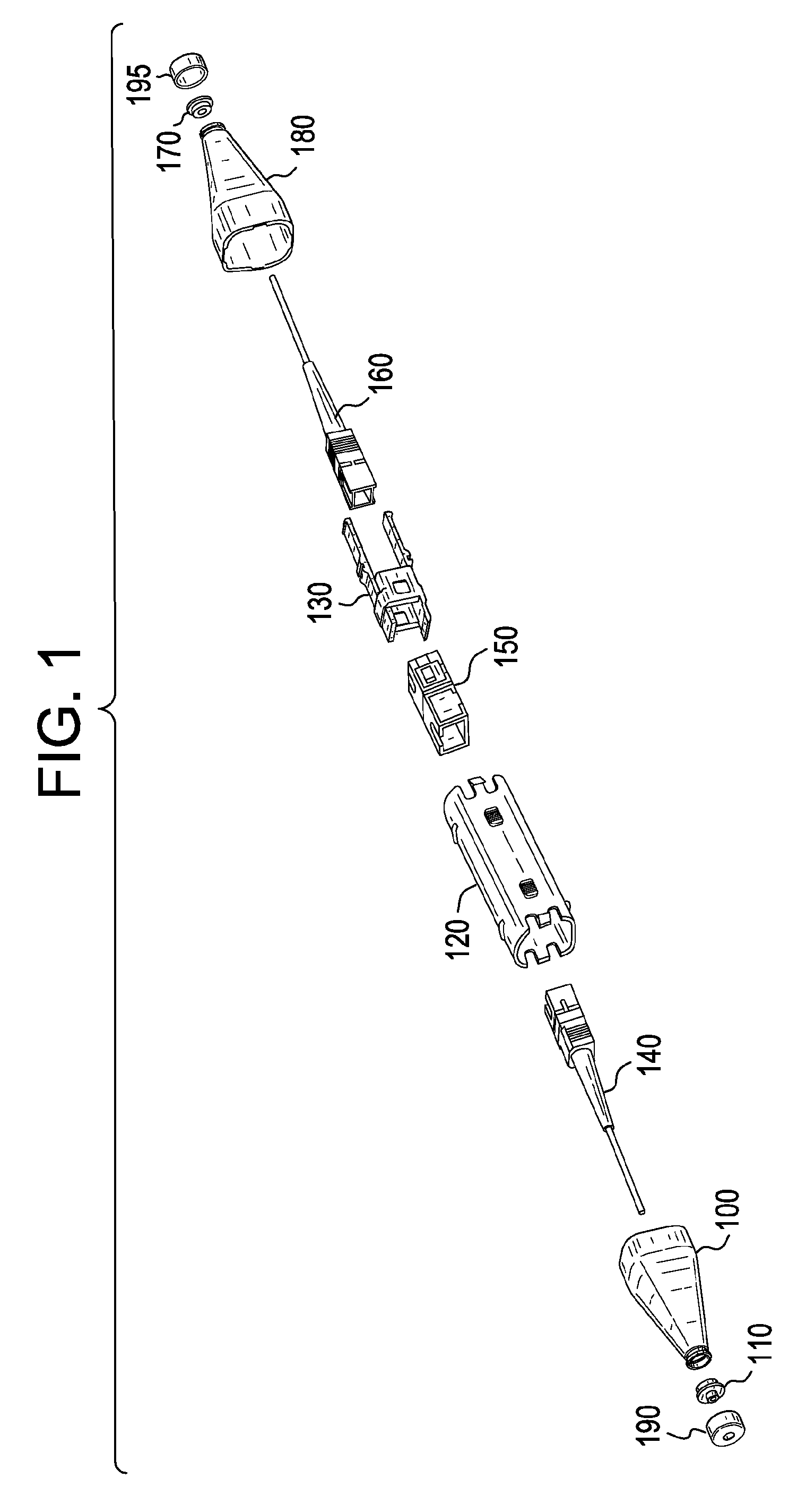
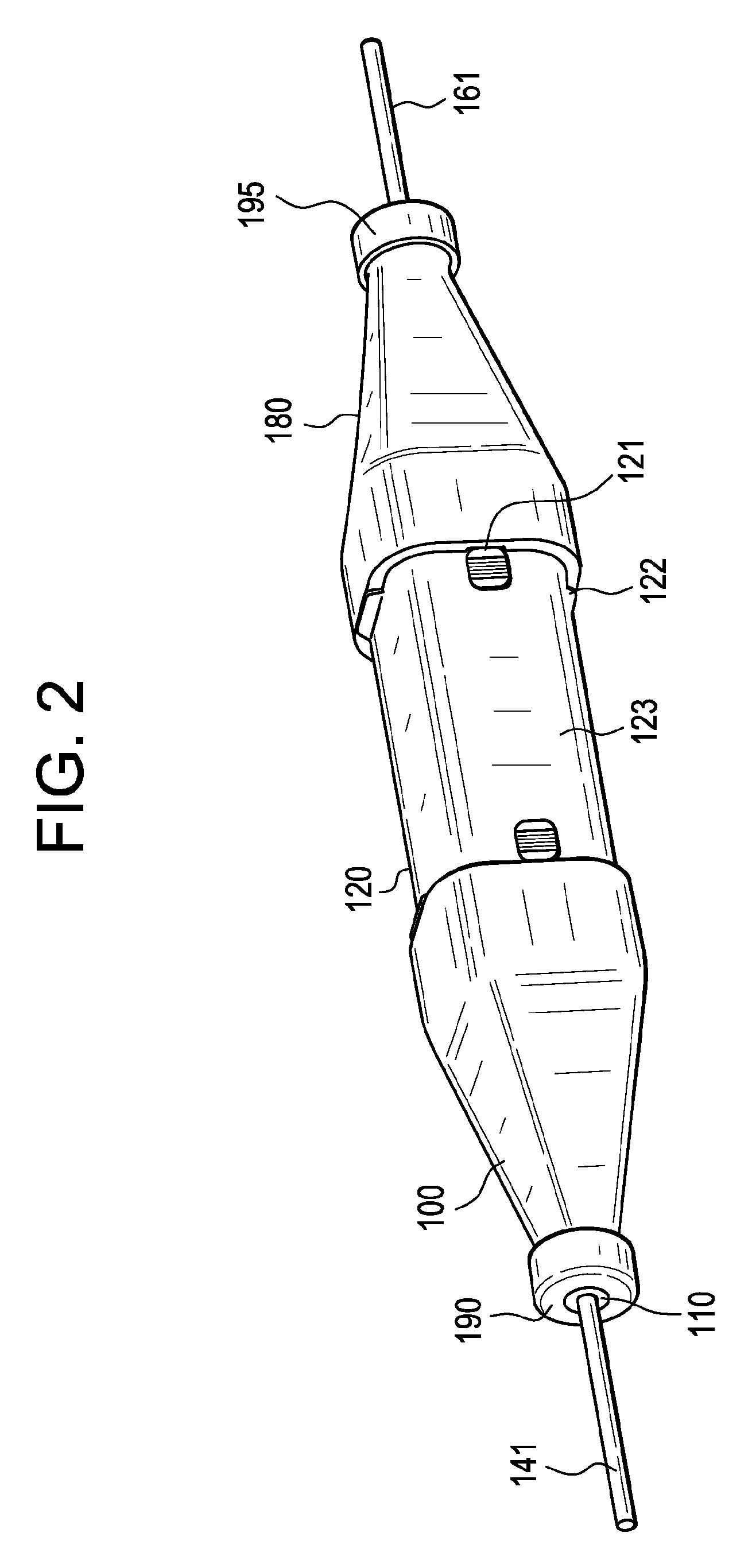
A connector housing apparatus for allowing field engineers or technicians to run cable point to point, and to protect the connection in an environmentally sealed, crush resistant housing is provided. The connector housing apparatus includes a connector housing body, two sealing boots, two sealing elements, two seal nuts, a fiber optic adapter, a fiber optic adapter insert that holds the fiber optic adapter and two fiber optic pigtails connected to two fiber optic cables. Each boot has two seal points. The first seal is between the fiber optic cable, the sealing element, the seal nut and the tapered portion of the sealing boot. The second seal is between the snap finger on the sealing boot and the receiving catch on the connector housing body.

Description

CROSS-REFERENCE TO RELATED APPLICATIONS[0001]This application is based upon and claims the benefit of priority from U.S. Provisional Application No. 61 / 716,003, filed Oct. 19, 2012 in the United States Patent and Trademark Office, the disclosures of which are incorporated herein in its entirety by reference.BACKGROUND[0002]1. Field[0003]The invention is related to a connector housing, and more particularly to a small form factor field installable outside plant connector housing.[0004]2. Related Art[0005]The background information provided herein is for the purpose of generally presenting the context of the disclosure. Work of the presently named inventor, to the extent it is described in this background section, as well as aspects of the description that may not otherwise qualify as prior art at the time of filing, are neither expressly nor impliedly admitted as prior art against the present disclosure.[0006]In the Private Network and Industrial markets, there is a continuing trend ...

Claims


Application Information

Patent Timeline
IPC IPC(8): G02B6/38
CPCG02B6/3825G02B6/3887G02B6/3893G02B6/3816G02B6/4248G02B6/38875
Inventor LICHOULAS, TEDKIMBRELL, EDDIETURNER, CHUCKPOLIDAN, STEVE
Owner AFL COMM LLC
Learn More