Clipping machine with improved handling of suspension elements

a technology of suspension elements and clipping machines, which is applied in the field of clipping machines, can solve the problems of suspension elements being improperly fixed to sausage-shaped products, ejecting suspension elements from the lower die of the closing tool, and wasting production time, so as to improve the reliability of engagement.

Active Publication Date: 2015-08-13
POLY CLIP SYST
View PDF4 Cites 5 Cited by
  • Summary
  • Abstract
  • Description
  • Claims
  • Application Information

AI Technical Summary

Benefits of technology

[0007]Thus, it is an object of the present invention to eliminate or at least reduce the above mentioned risk and to provide a clipping machine having an improved reliability and accuracy when attaching a suspension element to a product.

Problems solved by technology

In these prior art feeding devices for flexible suspension elements there is a risk, however, that the suspension elements may be ejected from the lower die of the closing tools or from the clip by the impulse that is imparted to them when they are detached from the carrier strip.
This leads to the suspension elements not being properly fixed to the sausage-shaped product.
Unwanted downtime and lost production are the consequence.
The suspension elements twirling about can also catch in other parts of the machinery, which likewise results in additional downtime and lost production.
However, if small or short suspension elements are to be attached to the product, the moving distance of the of the closing tool pulling the suspension element off the carrier strip may be longer than the length of the suspension element covered by or arranged under the holding down element, so that the suspension element is drawn away from the guiding device before the clip is closed by the closing tools.
Thus, there is still a risk that the suspension element may be subjected to uncontrolled movements and may even jump out of the clip or the closing tool before the clip is closed.

Method used


Image

  • Clipping machine with improved handling of suspension elements
  • Clipping machine with improved handling of suspension elements
  • Clipping machine with improved handling of suspension elements

Examples


Embodiment Construction

[0025]In the following, a preferred embodiment of the clipping machine will be explained with reference to the drawing figures.

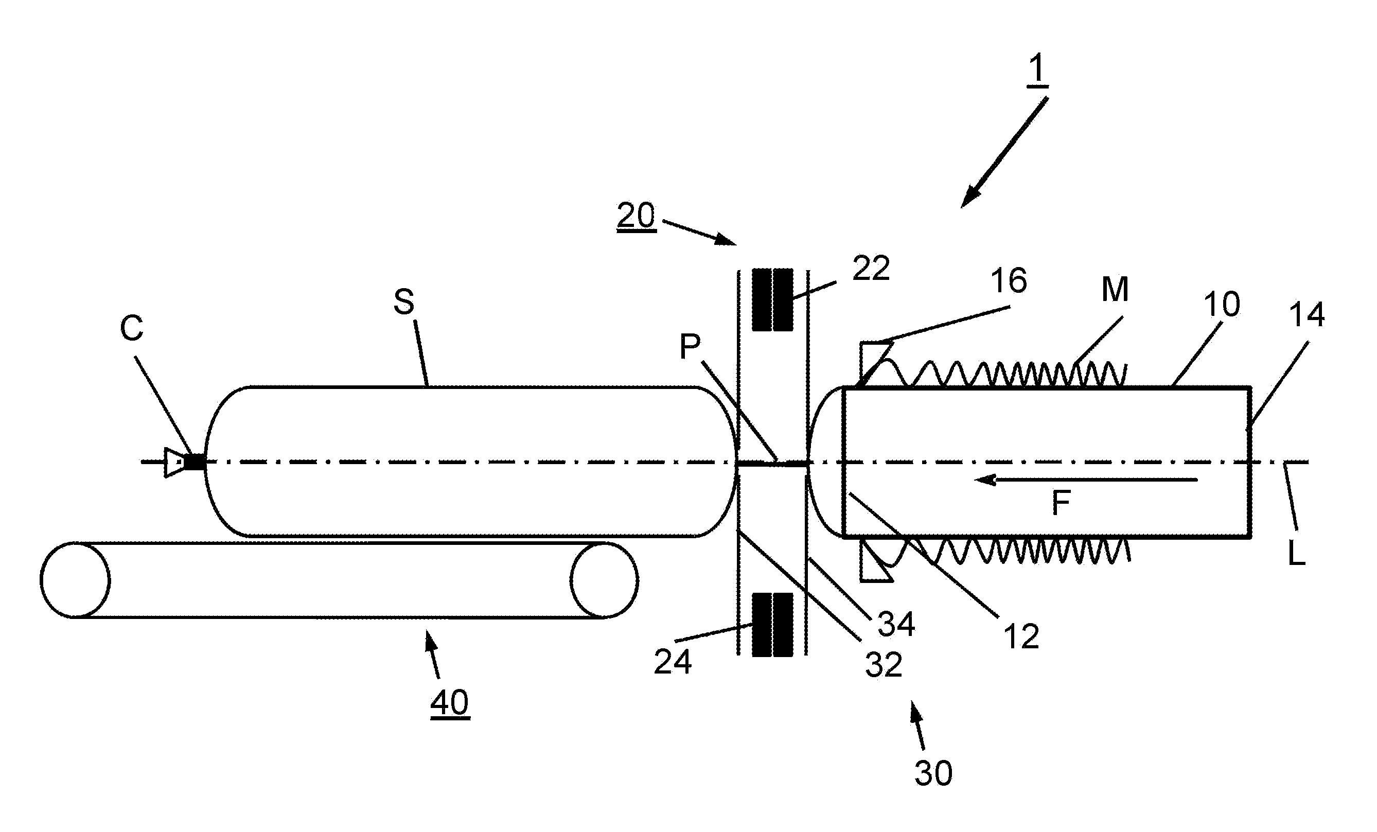
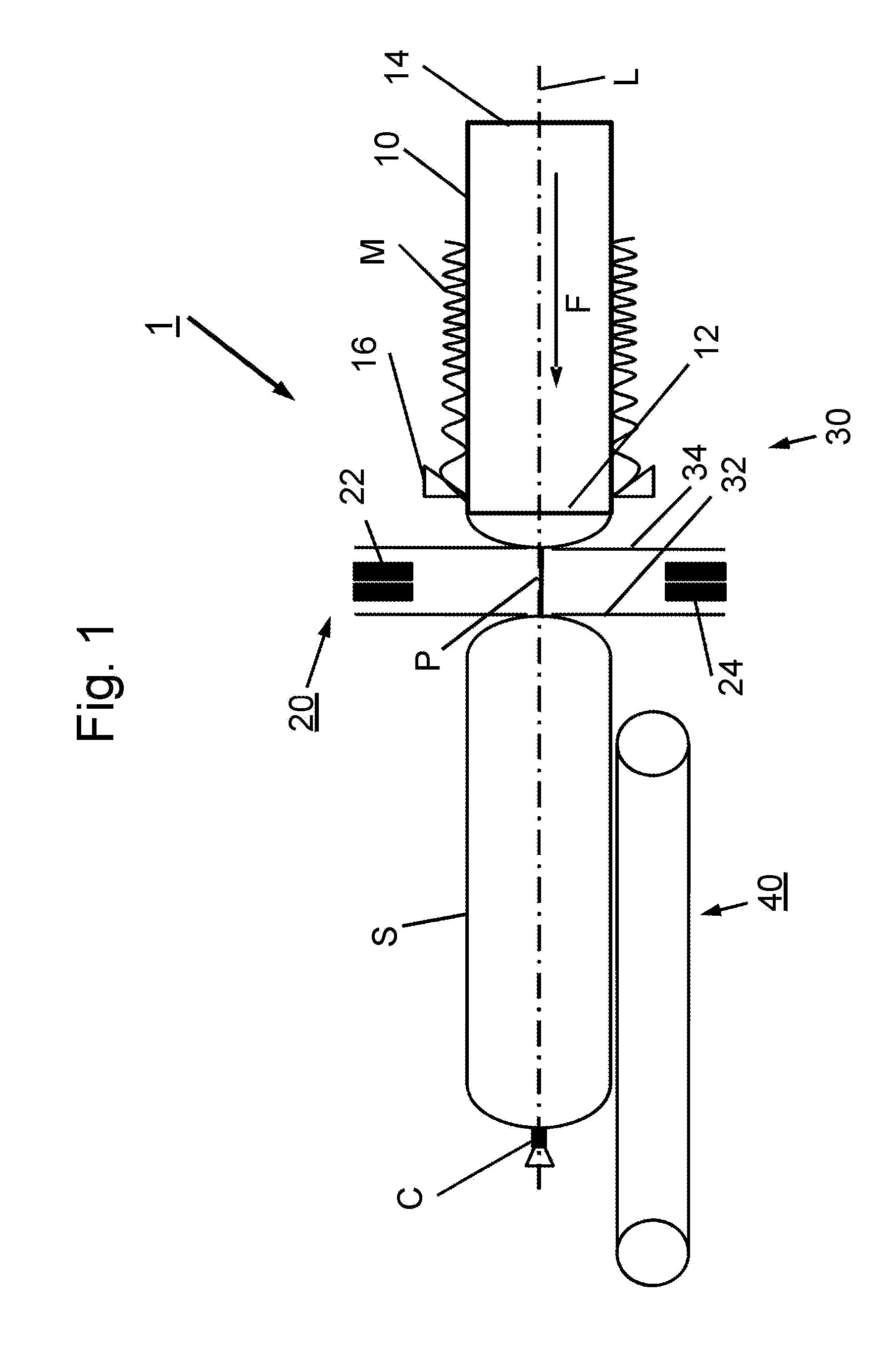
[0026]The clipping machine 1 for producing sausage-shaped products S according to FIG. 1, comprises as main components a circular cylindrical filling tube 10 having a longitudinally extending central axis A and being made of stainless steel, wherein tubular packaging casing M made of a thin sheet material is stored on the filling tube 10, gathering means 30 for gathering the filled tubular packaging casing M and for forming a plait-like portion thereto are arranged downstream filling tube 10, and a clipping device 20 for closing the filled tubular packaging casing M by applying a closure means, like a closure clip C, to said plait-like portion P.

[0027]As it can be inferred from FIG. 1, horizontally arranged filling tube 10 has a left end 12 facing clipping device 20 and a right end 14 coupled to a filler arrangement (not shown in FIG. 1) including a pump for...


PUM


Abstract

A clipping machine for producing sausage-shaped products (S), like sausages, by filing a flowable filling material into a tubular or bag-shaped packaging casing (M) and closing said packaging casing (M) by a closure means, like a closure clip (C). The clipping machine (1) comprises a feeding device (50) for suspension elements configured to feed suspension elements (E) attached to a carrier strip (B) to a delivery position and to place a first section of a suspension element (E) within the closure means (C) positioned on the die (25) of the second closing tool (24). The feeding device (50) further comprises a guiding device (51) configured to hold down the suspension element (E) close to the carrier strip (B) while the suspension element (E) is pulled off and detached from the carrier strip (B) by a relative movement between the second clipping tool (24) and the feeding device (50). A holding device (60) attached to the second clipping tool (24) is configured to releasably receive and hold a second section of the suspension element (E) when detached from the carrier strip (B).

Description

RELATED APPLICATION[0001]This application claims the benefit of priority of European Patent Application No. 14154881.8-1655 filed Feb. 12, 2014, the contents of which are incorporated herein by reference in their entirety.FIELD AND BACKGROUND OF THE INVENTION[0002]The present invention relates to a clipping machine for producing sausage-shaped products, according to the preamble of independent claim 1.[0003]In particular, the present invention relates to a clipping machine for producing sausage-shaped products, like sausages, by filing a flowable filling material into a tubular or bag-shaped packaging casing and closing said packaging casing by a closure means, like a closure clip. The clipping machine comprises a filling tube for feeding the filling material into the tubular or bag-shaped packaging casing stored on the filling tube and closed at its first end, gathering means for gathering the filled tubular or bag-shaped packaging casing and for forming a plait-like portion theret...

Claims


Application Information

Patent Timeline
Patent Type & Authority Applications(United States)
IPC IPC(8): A22C11/12A22C11/02
CPCA22C11/02A22C11/125A22C11/127A22C15/002
Inventor EBERT, DETLEFWURTH, THORSTEN
Owner POLY CLIP SYST
Why Eureka
Try Eureka