Nebulized ventilation system

Inactive Publication Date: 2015-08-13
PNEUMOFLEX SYST
View PDF5 Cites 23 Cited by
  • Summary
  • Abstract
  • Description
  • Claims
  • Application Information

AI Technical Summary

Benefits of technology

[0008]In yet another example, the medication receiver is formed as a cylindrical wall member carried on the outer surface of the tubular nebulizer housing. The suction line extends into the area defined within the cylindrical wall member. A medication container is received within the cylindrical wall member of the medication receiver and dimensioned to hold medication that is drawn upward through the suction line. A twist lock slot is formed in the cylindrical wall member and a lock protrusion is formed on the medication container that is received in the twist lock slot to lock the medication container within the medication receiver. A valve communic

Problems solved by technology

Such debilitating problems may result from pneumonia, COPD, upper spinal chord injuries, polio, Amyotrophic Lateral Sclero

Method used


Image

  • Nebulized ventilation system
  • Nebulized ventilation system
  • Nebulized ventilation system

Examples


Embodiment Construction

[0020]Different embodiments will now be described more fully hereinafter with reference to the accompanying drawings, in which preferred embodiments are shown. Many different forms can be set forth and described embodiments should not be construed as limited to the embodiments set forth herein. Rather, these embodiments are provided so that this disclosure will be thorough and complete, and will fully convey the scope to those skilled in the art.

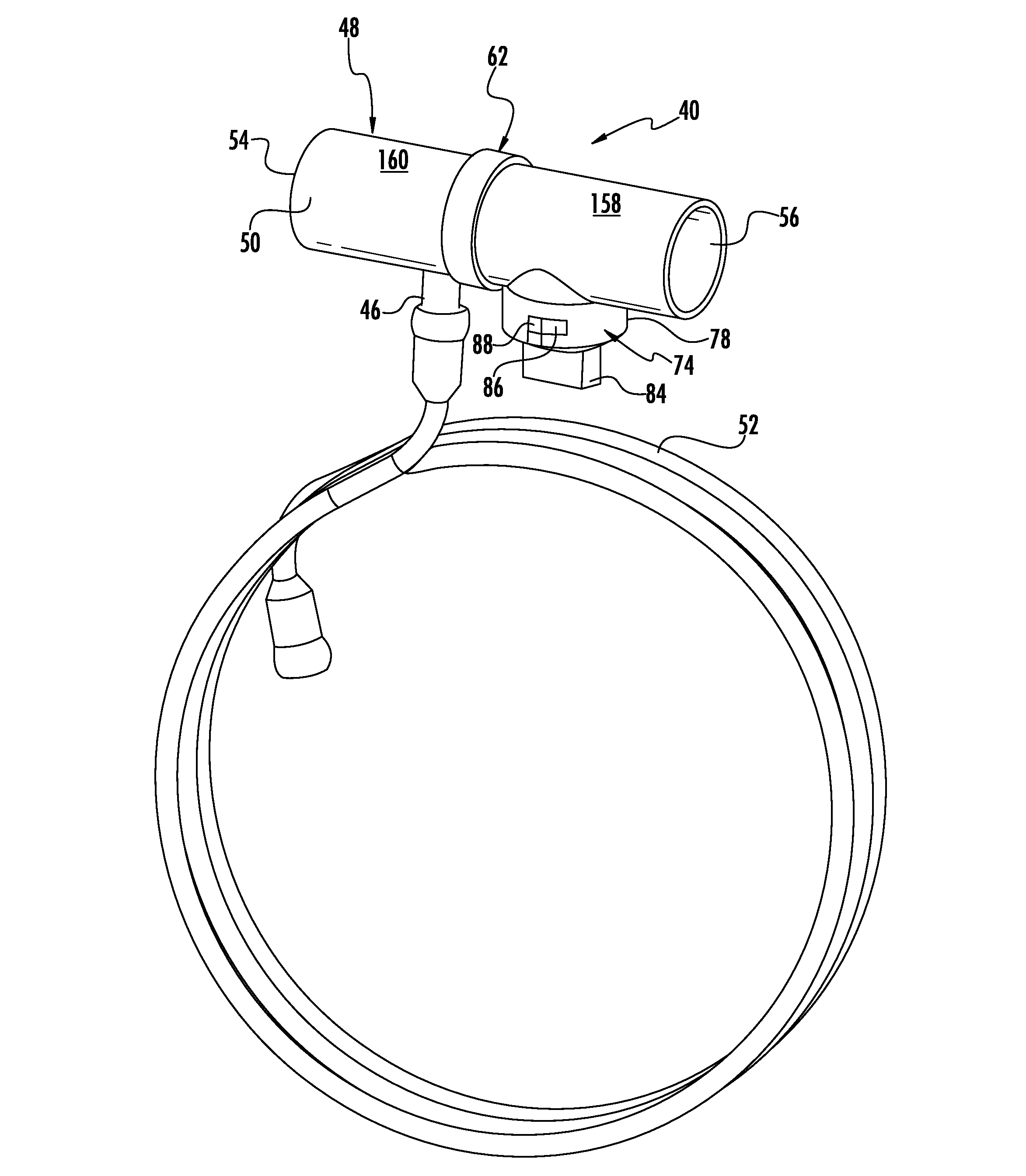
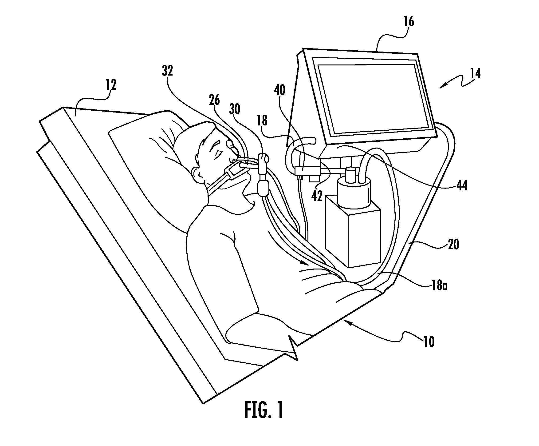
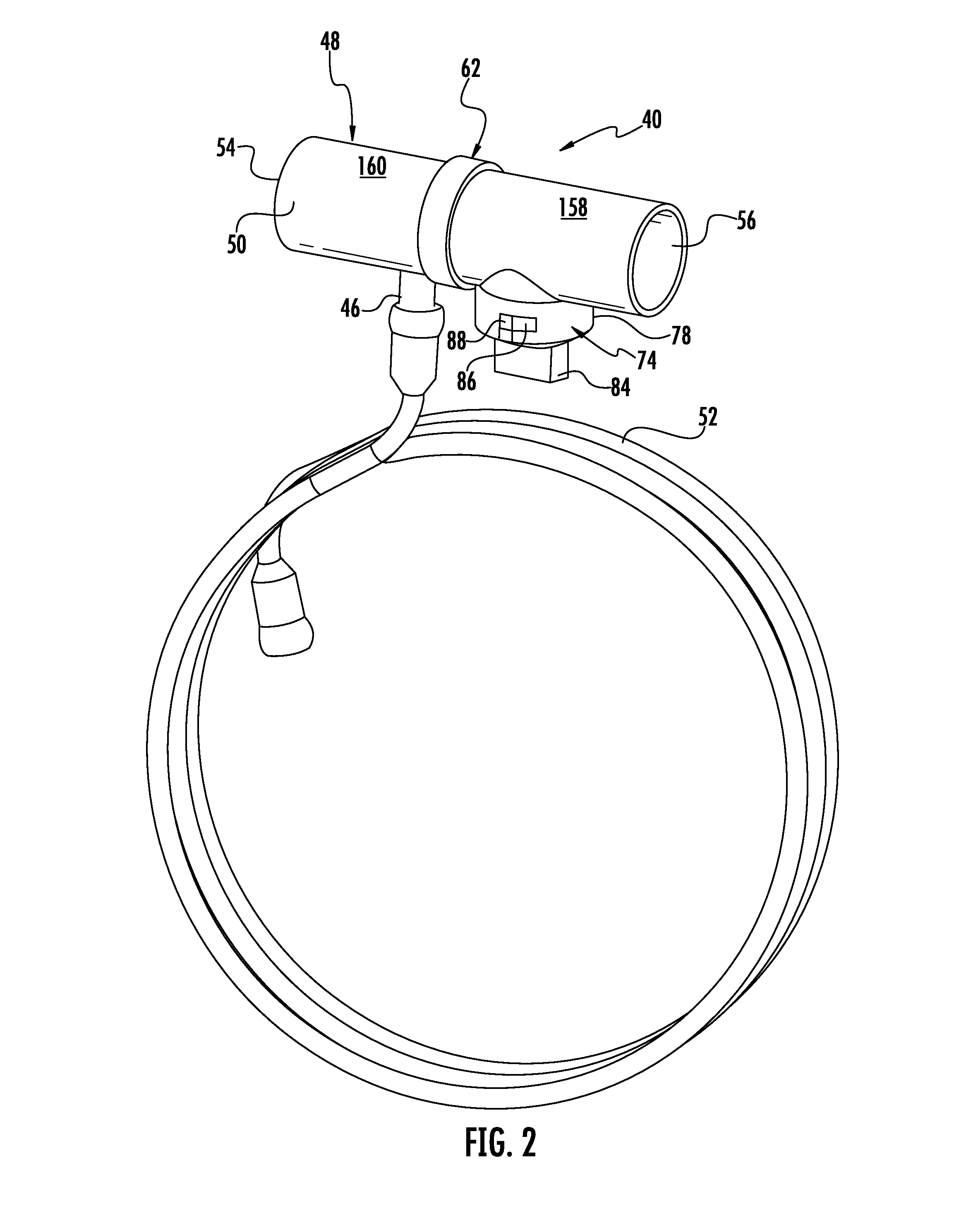
[0021]FIG. 1 is a fragmentary, perspective view showing a patient 10 in a hospital or other medical setting and lying inclined on a bed 12 and mechanically assisted in spontaneous breathing using a mechanical ventilation system indicated generally at 14 that includes a ventilator 16 and an inspiratory air line 18 connected to the ventilator through which pressurized air is provided to a patient from the ventilator. An expiratory air line 20 returns air and is connected back into the ventilator 16. As illustrated, the inspiratory air line is ...


PUM


Abstract

A nebulizer is connected to an inspiratory air line of a ventilator and forms an air path along a longitudinal axis through which air is delivered to a patient from a ventilator. A nebulizer nozzle is carried within the nebulizer housing and aligned with the longitudinal axis through which gas is mixed with medication and discharged into the air path. A suction line extends from the discharge end of the nebulizer nozzle through the outer surface of the nebulizer housing to a medication receiver that draws medication upward from a medication container contained within the medication receiver and mixes the medication with gas passing through the nebulizer nozzle and nebulizes the medication for discharge into the air path to a patient.

Description

FIELD OF THE INVENTION[0001]The present invention relates to medical ventilators used to assist breathing in a patient, and more particularly, this invention relates to nebulizers used with mechanical and other medical ventilators.BACKGROUND OF THE INVENTION[0002]Medical ventilators mechanically move breathable air into and out of a patient's lungs and provide the mechanism of breathing for the patient, who typically is physically unable to breathe or is breathing insufficiently. Positive pressure ventilators are common where air or another gas mixture is forced by pressure into the trachea using an endotracheal tube that rests in the trachea and usually held in position by an inflatable balloon positioned at the end of the endotracheal tube, which allows the endotracheal tube to sit securely in the airway. The positive pressure ventilator works by increasing the patient's airway pressure through the endotracheal tube or in some examples, through a tracheostomy tube that allows the ...

Claims


Application Information

Patent Timeline
IPC IPC(8): A61M16/14A61M15/00A61M16/20A61M16/16A61M16/00A61M16/08
CPCA61M16/147A61M16/0012A61M16/0816A61M15/0086A61M16/20A61M16/16A61M16/0875A61M11/06A61M16/127
Inventor ADDINGTON, W. ROBERTMILLER, STUART P.
Owner PNEUMOFLEX SYST
Why Eureka
Try Eureka