
Railway inspection system

Inactive Publication Date: 2015-08-13
ELECTRO-MOTIVE DIESEL
View PDF9 Cites 33 Cited by
  • Summary
  • Abstract
  • Description
  • Claims
  • Application Information

AI Technical Summary

Benefits of technology

The patent is for a system that allows an unmanned vehicle to inspect and detect any problems with a railway track, such as pothaws or cracks. This system can travel on the track in front of a train and communicate the information about any problems to the train's control system. This allows for quicker detection and repair of issues, which can prevent accidents and improve safety.

Problems solved by technology

Generally, railway inspection systems are often limited by human ability to visually and audibly inspect trains to operate on track.
Although visual inspections are currently governed by Federal Railroad Administration (FRA) regulations, as set forth in Part 213 of 49 CFR, it may not allow the operator to detect minor track defects before the lead locomotive travels over the defective track.
The use of this visual inspection system may become further complicated when the track is exposed to additional factors such as corrosion, rust, extreme weather and locomotive operating conditions during the course of travel.
Additionally, cracks in the rail, loose spikes, defective ties, weed or growth near the tracks, brush or other growth blocking signals, and weakness in ballasts may further contribute to defects of railway conditions.
Also, an operator may hear what he or she believes to be an unusual noise, which may indicate a problem with railway track structure.
Thus, track defects, as well as obstacles on or near the track may become difficult to for an operator of a locomotive in a train to visually and / or audibly ascertain, in order to detect and avoid, thus potentially minimizing damage to the track, track infrastructure and possibly the train.
While the pilot vehicle of Cooper may be capable of monitoring and recording defective railway track condition by video, it may not be remotely controlled by the train nor does it provide information regarding audio defects in track conditions.
Moreover, this system does not provide information regarding visual or audio defects that could be remotely controlled to a back office location.

Method used


Image

  • Railway inspection system
  • Railway inspection system
  • Railway inspection system

Examples


Embodiment Construction

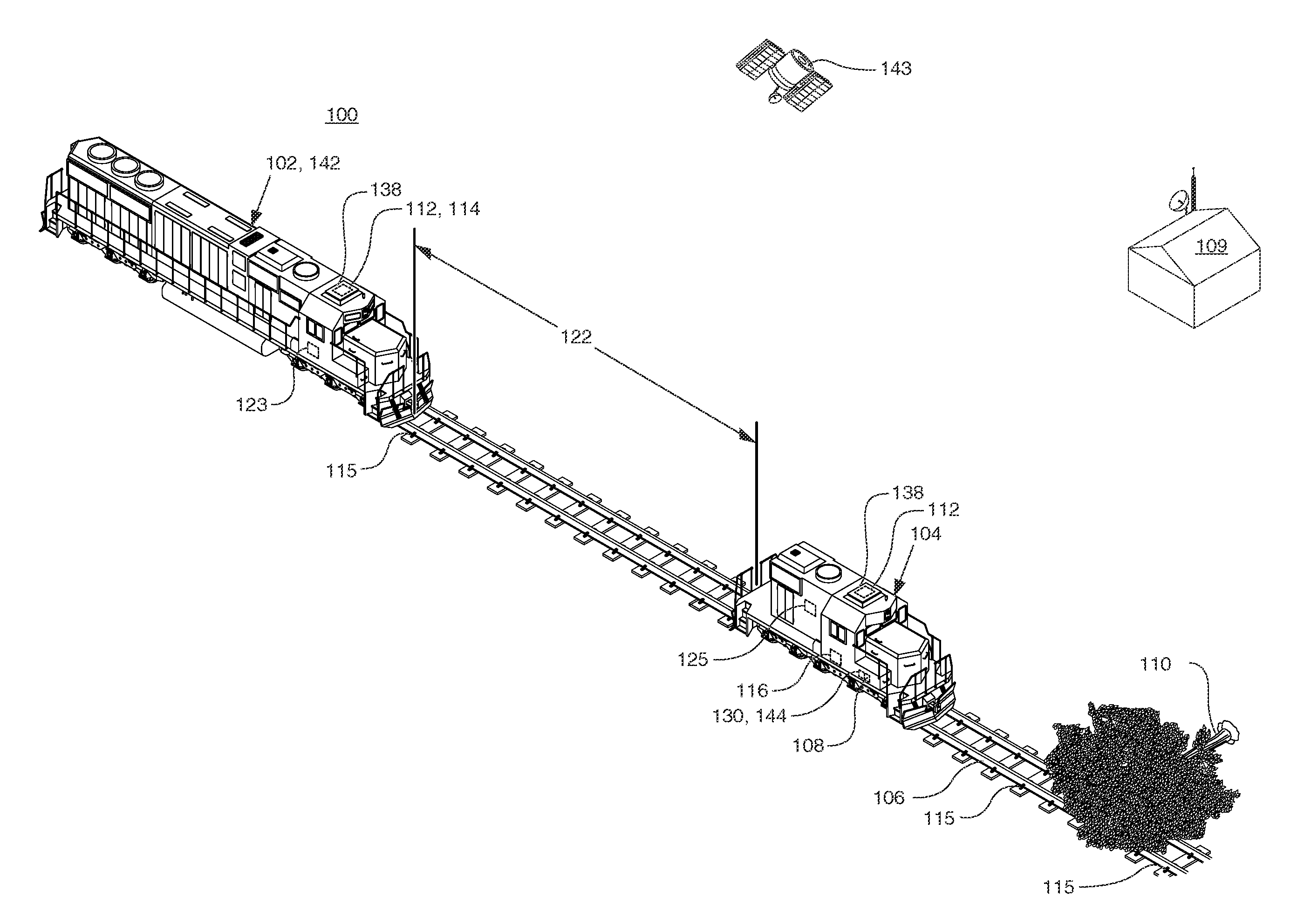
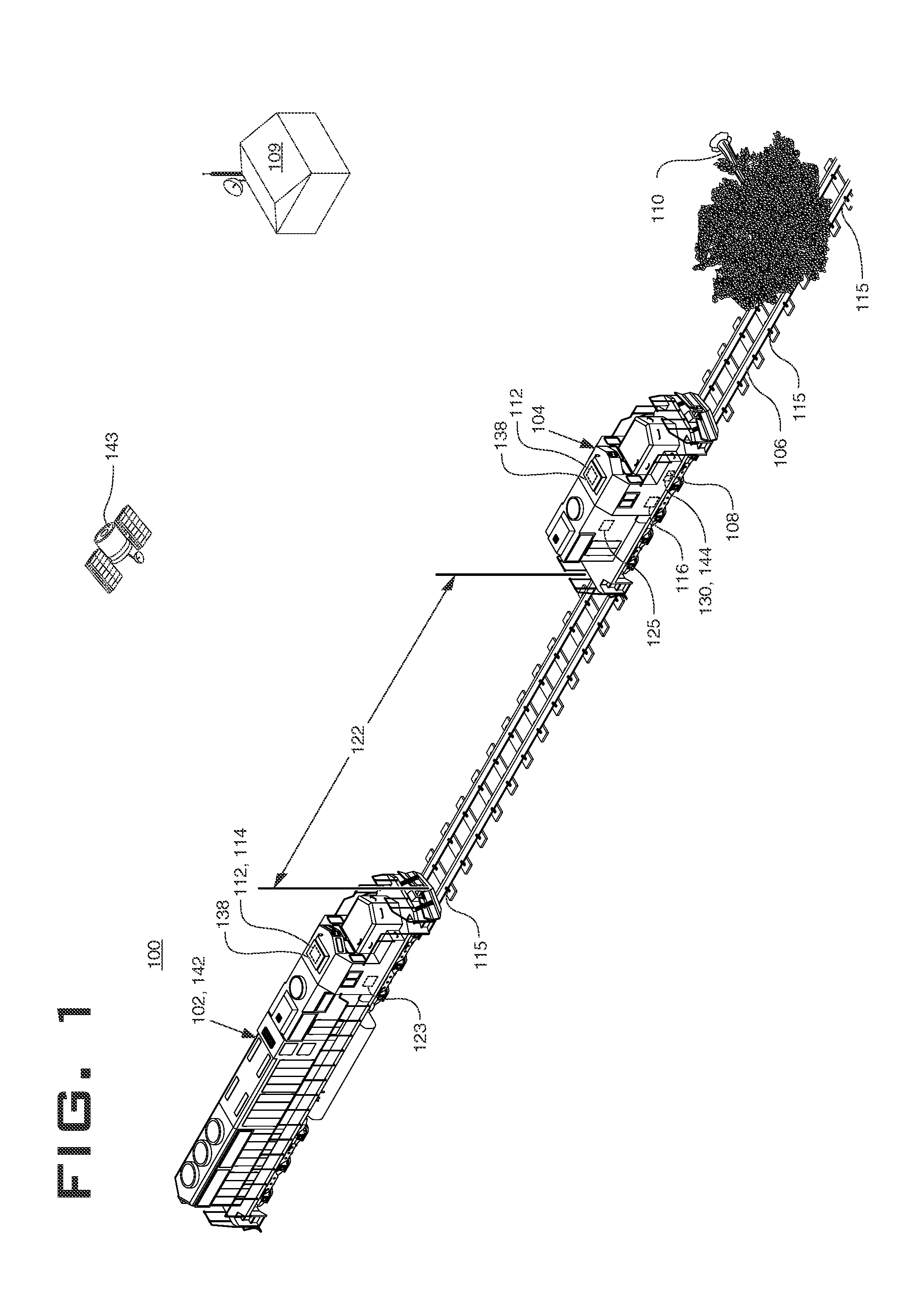
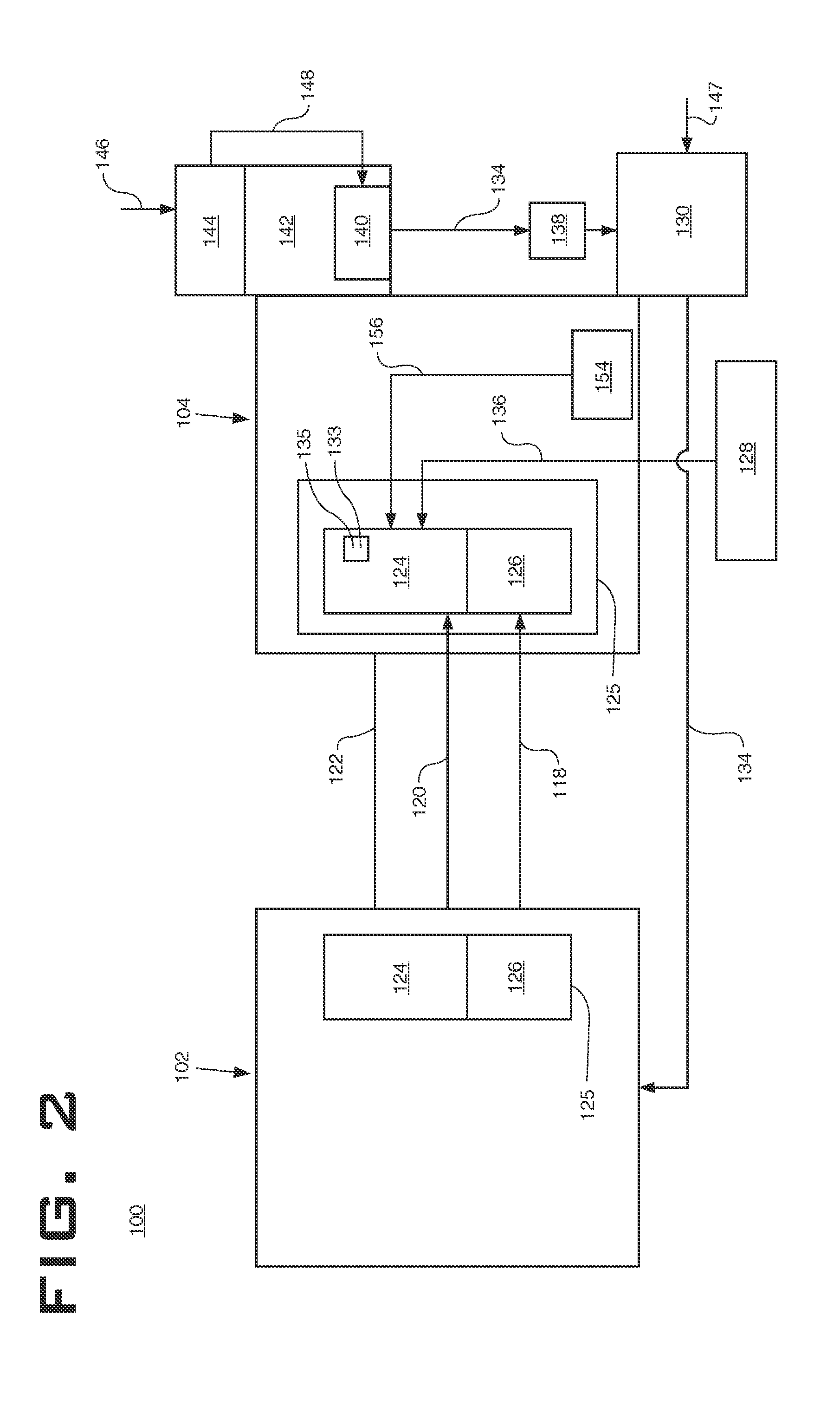
[0011]FIG. 1 is an illustration of a railway inspection system 100 for a train 102. The railway inspection system 100 includes an unmanned self-propelled vehicle 104, a sensor 108, a positioning system 112 and a controller 116. The unmanned self-propelled vehicle 104 is adapted to travel on a railway track 106 ahead of the train 102. The unmanned self-propelled vehicle 104 may be powered by a drive means 125, fueled by diesel fuel, battery or the like. The unmanned self-propelled vehicle 104 may also be powered by an independent propulsion system (not shown) that may be remotely controlled by the train. Alternatively, the unmanned self-propelled vehicle 104 may be remotely controlled by a back office 109. The sensor 108 is configured to detect an adverse railway condition 110. The sensor 108 may be designed for detecting a condition of the railway track 106, such as washed out or a breakage of rail of the railway track 106. The sensor 108 may be a magnetic, ultrasonic, sonic or othe...


PUM


Abstract

In one aspect of the present disclosure, a railway inspection system is shown. The system includes: an unmanned self-propelled vehicle, a sensor, a position system and a control system. The unmanned self-propelled vehicle is adapted to travel on a railway track ahead of the train and has a sensor configured to detect an adverse railway condition. The positioning system is configured to determine the position of the self-propelled vehicle. The control system in communication with the sensor and the train; wherein the control system communicates the adverse railway condition to the train.

Description

TECHNICAL FIELD[0001]The present disclosure relates generally to a system, and more particularly, to railway inspection system which includes an unmanned self-propelled vehicle, a positioning system and a control system.BACKGROUND[0002]Generally, railway inspection systems are often limited by human ability to visually and audibly inspect trains to operate on track. For example, visual inspection may occur when an operator transverses railway track on foot or manually operates the lead locomotive in a train. Although visual inspections are currently governed by Federal Railroad Administration (FRA) regulations, as set forth in Part 213 of 49 CFR, it may not allow the operator to detect minor track defects before the lead locomotive travels over the defective track. It also relegates the lead locomotive of a train to travel at a very slow speed (e.g., not more than five miles per hour when passing over track crossings, highway crossing and switches), for a limited track distance (e.g...

Claims


Application Information

Patent Timeline
IPC IPC(8): B61L23/04
CPCB61L23/041
Inventor BRANKA, SCOTT M.KELLEHER, RAY T.
Owner ELECTRO-MOTIVE DIESEL
Learn More