Controller and control method for engines

a control method and engine technology, applied in the direction of electric control, engine starters, instruments, etc., can solve the problems of increasing the amount of fuel injection, increasing the torsion of the crankshaft, and deteriorating the learning accuracy, so as to improve the learning accuracy

Inactive Publication Date: 2015-08-13
MAZDA MOTOR CORP
View PDF23 Cites 6 Cited by
  • Summary
  • Abstract
  • Description
  • Claims
  • Application Information

AI Technical Summary

Benefits of technology

[0008]It is therefore an object of the present invention to, during learning of a characteristic of an engine control-related component for use in engine control, allow an engine to be reliably maintained in a no-load state and kept in a stable state to thereby enhance learning accuracy.
[0011]The present invention can, during learning of a characteristic of an engine control-related component for use in engine control, allow an engine to be reliably maintained in a no-load state and kept in a stable state to thereby enhance learning accuracy.

Problems solved by technology

This is because, if a load is applied to the engine, it results in an increase in fuel injection amount, or an increase in torsion of a crankshaft, which is likely to cause deterioration in learning accuracy.
Further, a microprocessor for executing the learning also consumes electricity by itself.
Excessive lowering of the SOC accelerates degradation of the battery.
When the alternator is activated during execution of the learning, an operation of the alternator causes an increase in load on the engine, wherein the load unpredictable fluctuates.
As a result, the learning accuracy deteriorates.

Method used


Image

  • Controller and control method for engines
  • Controller and control method for engines
  • Controller and control method for engines

Examples


Embodiment Construction

[0019]The present invention will now be described in detail through an embodiment thereof.

[0020](1) Overall Configuration

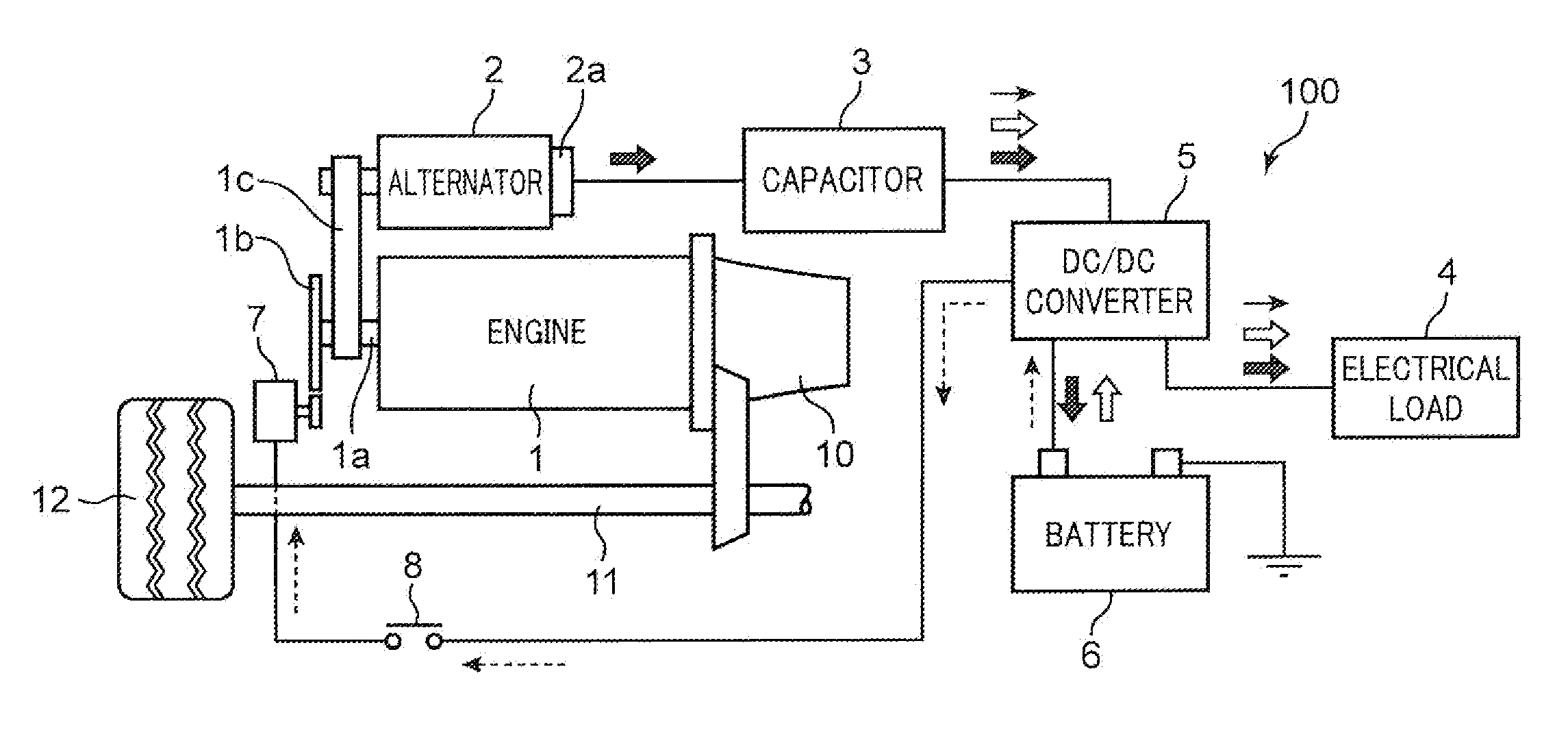
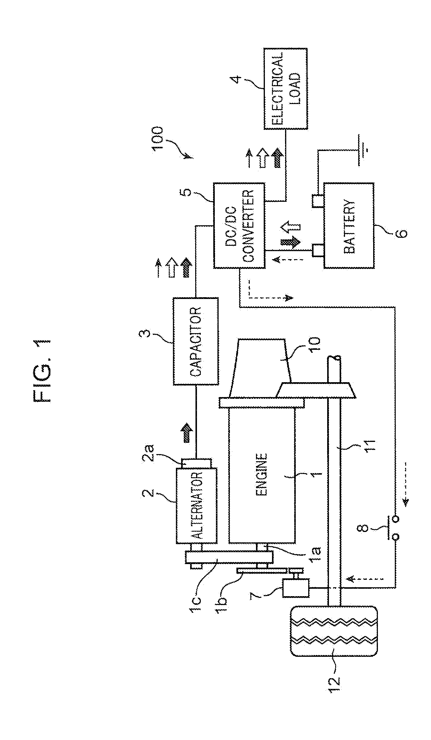
[0021]FIG. 1 is a block diagram of an engine 1 and an electricity supply system 100 which pertain to one embodiment of the present invention. As illustrated in FIG. 1, a vehicle pertaining to this embodiment is equipped with: an engine (in this embodiment, diesel engine) 1 serving as a traveling drive source; an alternator 2 (equivalent to “electricity generation device” set forth in the appended claims) configured to acquire a motive force from the engine 1 to generate electricity; a capacitor 3 electrically connected to the alternator 2 to store therein the electricity generated by the alternator 2; an electrical load 4; a DC-DC converter 5; a battery 6 serving as an electricity source; and a starter motor 7 capable of giving a rotational force to the engine 1 during start of the engine 1. Examples of the electrical load 4 include an air conditioner 21 (see FIG....


PUM


Abstract

An alternator configured to acquire a motive force from an engine to generate electricity and a capacitor capable of storing therein the electricity generated by the alternator are provided. An electricity consumption amount required during learning is calculated, and a capacitor electricity amount is compared with the calculated electricity consumption amount, and when the capacitor electricity amount is equal to or less than the calculated electricity consumption amount, the alternator is operated to generate electricity until the capacitor electricity amount is increased beyond the calculated electricity consumption amount. On the other hand, when the capacitor electricity amount is greater than the calculated electricity consumption amount, or when the capacitor electricity amount is increased beyond the calculated electricity consumption amount according to electricity generation by the alternator, the learning is performed while using the capacitor electricity without performing electricity generation by the alternator.

Description

TECHNICAL FIELD[0001]The present invention relates to an engine control apparatus and method, and more specifically to an engine control apparatus and method for learning a characteristic of an engine control-related component such as a fuel injection valve, for use in engine control such as fuel injection control.BACKGROUND ART[0002]Heretofore, along with the progress of automotive electronics, for example, fuel injection control such as fuel injection amount control and fuel injection timing control has been performed by an electronic control system mainly composed of a microprocessor. A characteristic of a fuel injection valve (a relationship between an assignable injection time period to the fuel injection valve and an actual injection amount) for use in the fuel injection control has a variation due to individual differences among fuel injection valves, aging, etc. In this connection, there has been known a technique of learning a characteristic of a fuel injection valve so as ...

Claims


Application Information

Patent Timeline
Patent Type & Authority Applications(United States)
IPC IPC(8): F02D41/24F02D29/02
CPCF02D29/02F02D41/2451F02D41/08F02D41/042F02D41/2467F02D41/403F02N11/0866F02N2200/061Y02T10/40
Inventor HIRABAYASHI, KAZUNORIMITSUISHI, NAOYAOKAMOTO, SHINGOTATEISHI, MASAHIROKAMIMURA, TOSHIHIROOISO, ISSEIENSEKI, YOSHIAKI
Owner MAZDA MOTOR CORP
Why Eureka
Try Eureka