
Reciprocating compressor and method for driving same

a compressor and reciprocating technology, applied in the direction of positive displacement liquid engines, piston pumps, liquid fuel engines, etc., can solve the problems of degrading compressor performance, affecting the performance of compressors, and affecting the installation direction of compressors, so as to reduce vibration noise of compressors, improve compressor performance, and reduce specific volume of compression space

Active Publication Date: 2015-08-13
LG ELECTRONICS INC
View PDF2 Cites 7 Cited by
  • Summary
  • Abstract
  • Description
  • Claims
  • Application Information

AI Technical Summary

Benefits of technology

The present invention provides a reciprocating compressor that can prevent increased suction loss and heating of the cylinder by high-temperature refrigerant gas. This is done by cooling the high-temperature refrigerant gas through heat exchange with a sucked refrigerant in a separate inner space of the casing. The compressor also includes a guide guiding unit to reduce vibration and noise and a cylinder that can vibrate to remove foreign materials from gas holes, thereby preventing friction loss and abrasion.

Problems solved by technology

However, the supplying of the lubricant requires an oil supply apparatus, and an oil shortage may occur depending on operation conditions, thereby degrading compressor performance.
Also, the compressor size needs to be increased because a space for receiving a certain amount of oil is required, and the installation direction of the compressor is limited because the entrance of the oil supply apparatus should always be kept immersed in oil.
Also, as high-temperature refrigerant gas discharged from a compression space is introduced into the fluid bearing to heat the cylinder 2, a specific volume of a compression space increases and thereby a suction loss is caused.
Furthermore, discharge noise and vibration which are generated while a refrigerant compressed in the compression space is discharged cannot effectively be offset, thereby increasing vibration noise of the compressor.

Method used


Image

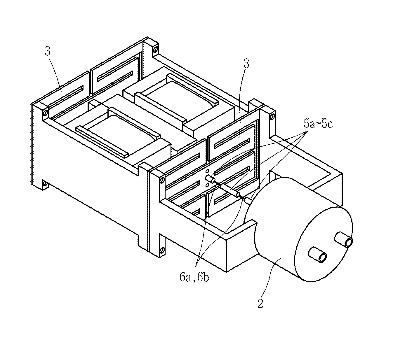
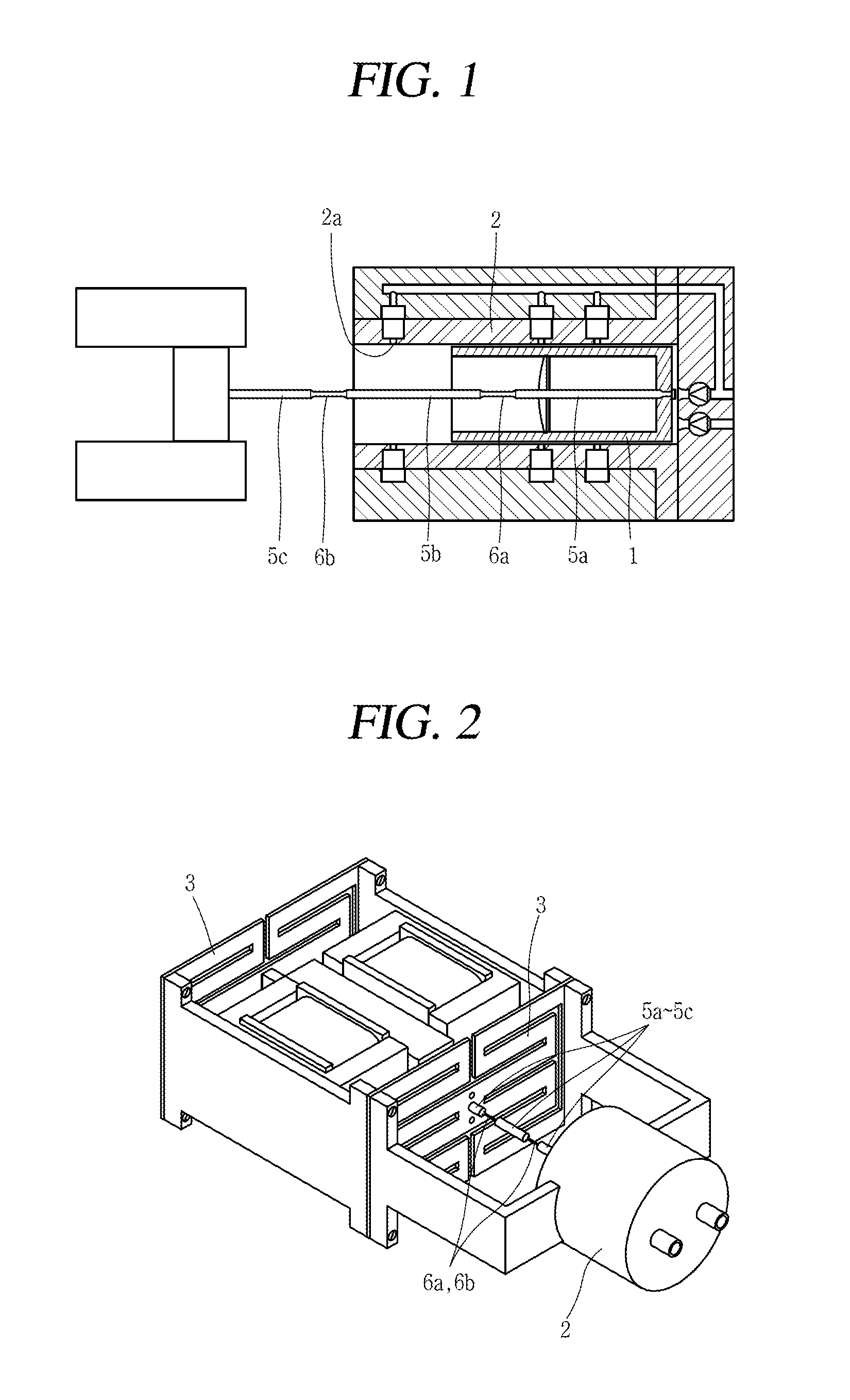
  • Reciprocating compressor and method for driving same
  • Reciprocating compressor and method for driving same
  • Reciprocating compressor and method for driving same

Examples


Embodiment Construction

[0032]Hereinafter, description will be given in detail of a reciprocating compressor according to one embodiment illustrated in the accompanying drawings.

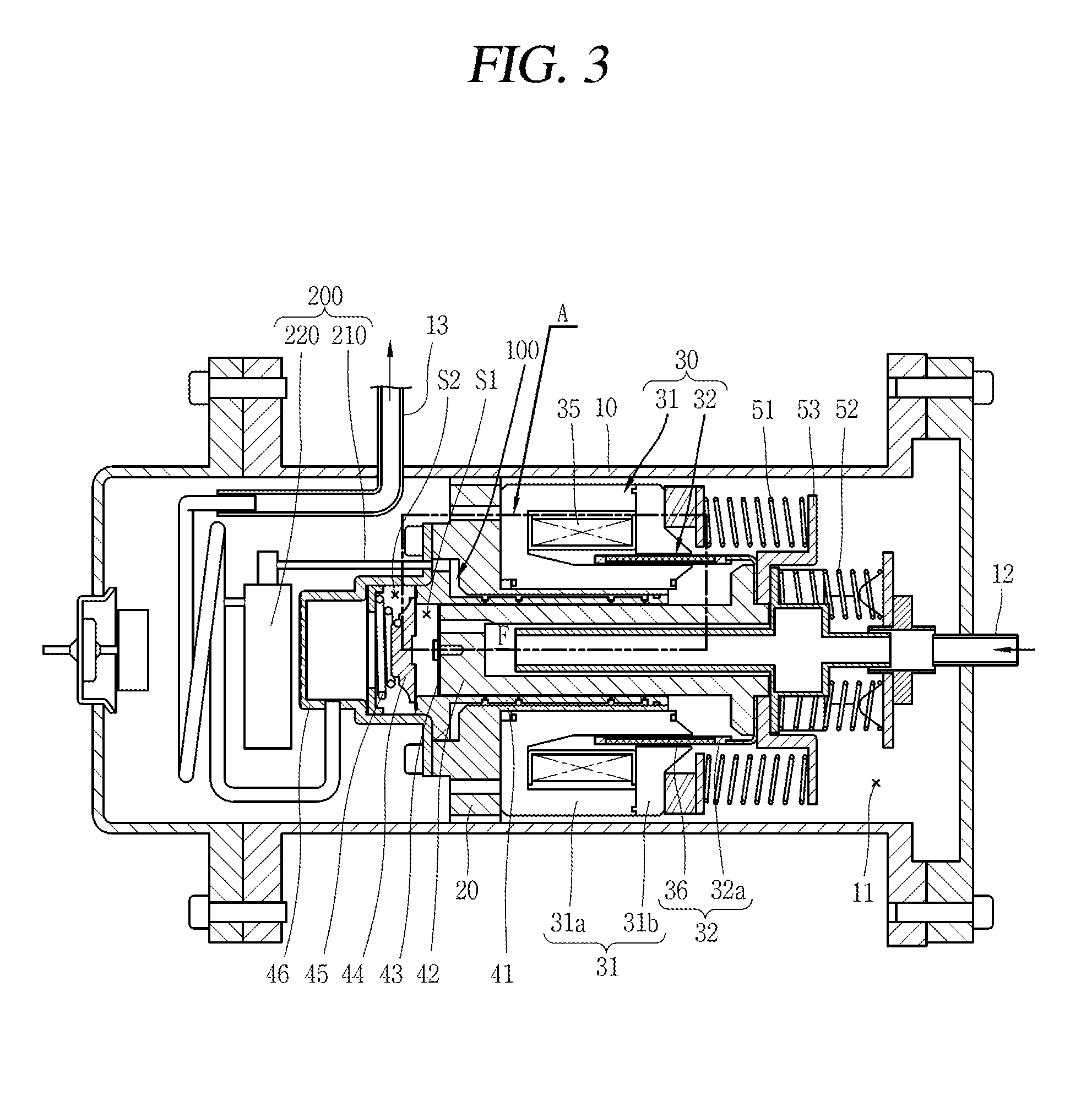
[0033]FIG. 3 is a longitudinal sectional view of a reciprocating compressor in accordance with the present invention.

[0034]As illustrated in FIG. 3, in a reciprocating compressor according to an embodiment disclosed herein, a suction pipe 12 may be connected to an inner space 11 of a casing 10, and a discharge pipe 13 may be connected to a discharge space S2 of a discharge cover 46 to be explained later. A frame 20 may be disposed in the inner space 11 of the casing 10. A stator 31 of a reciprocating motor 30 and a cylinder 41 may be fixed to the frame 20. A piston 42 which is coupled to a mover 32 of the reciprocating motor 30 may be inserted into the cylinder 41 so as to reciprocate therein. Resonant springs 51 and 52 for inducing a resonating motion of the piston 42 may be provided at both sides of the piston 42 in a motion dire...


PUM


Abstract

The present disclosure relates to reciprocating compressor. The present invention can prevent friction loss or abrasion between a cylinder and a piston, which is caused when a hydraulic bearing is blocked with a foreign substance, by preventing the foreign substance mixed in refrigerant gas from flowing into the hydraulic bearing, and can improve compressor performance by preventing a specific volume in a compression space from increasing when high-temperature refrigerant gas discharged in the compression space is cooled, such that vibration noise of the compressor can be reduced since a gas guiding part offsets vibration and the noise generated when a refrigerant is discharged in the compression space. Furthermore, the number of vibrations of a mover is increased and a driving operation for removing foreign substances is carried out to increase the number of vibrations of a cylinder such that any foreign substance stuck in a gas hole can be cleaned, thereby increasing performance and reliability of the compressor.

Description

TECHNICAL FIELD[0001]The present disclosure relates to a reciprocating compressor, and more particularly, a reciprocating compressor having a fluid bearing, and a method for driving the same.BACKGROUND ART[0002]Generally, a reciprocating compressor serves to intake, compress, and discharge a refrigerant as a piston linearly reciprocates within a cylinder. The reciprocating compressor may be classified into a connection type reciprocating compressor or a vibration type reciprocating compressor according to the method employed to drive the piston.[0003]In the connection type reciprocating compressor, the piston is connected to a rotating shaft associated with a rotation motor by a connection rod, which causes the piston to reciprocate within the cylinder, thereby compressing the refrigerant. On the other hand, in the vibration type reciprocating compressor, the piston is connected to a mover associated with a reciprocating motor, which vibrates the piston while the piston reciprocates...

Claims


Application Information

Patent Timeline
Patent Type & Authority Applications(United States)
IPC IPC(8): F04B17/03F04B53/10F04B53/00F04B53/20F04B35/04
CPCF04B17/03F04B35/04F04B53/20F04B53/10F04B53/004F04B39/0292F04B39/16F04B2205/501F04B49/065F04B35/045F04B49/20
Inventor KI, SUNGHYUNNOH, KIWONAHN, KWANGWOONPARK, KYEONGBAEJEON, SIMOONPARK, JOONSUNG
Owner LG ELECTRONICS INC
Learn More