Systems, apparatuses and methods for lifting, positioning and removing a bearing assembly from a shaft

a technology of bearing assembly and positioning device, which is applied in the direction of bearing repair/replacement, bearing rigid support, manufacturing tools, etc., can solve the problems of difficult replacement or service of bearings, affecting the service life or the frequency of maintenance of bearings, and affecting the service life of bearings. the effect of bearing assembly removal and convenient removal of bearing assembly

Inactive Publication Date: 2015-08-13
WEIR SLURRY GRP INC
View PDF7 Cites 11 Cited by
  • Summary
  • Abstract
  • Description
  • Claims
  • Application Information

AI Technical Summary

Benefits of technology

[0054]In a seventh aspect, a method for removing a bearing assembly from a shaft includes the steps of attaching a first end of at least one rod to the bearing assembly and a second opposed end to a base member. The method further includes the steps of positioning a drive member through the base member; aligning the base member such that the drive member contacts an end portion of the shaft; and moving the drive member to push against the shaft to cause the base member to move and, thus, the bearing assembly to move along a longitudinal axis of the shaft to facilitate removal of the bearing assembly from the shaft.
[0058]In an eighth aspect, a method for removing a bearing assembly from a shaft includes the steps of securing a first end of at least one rod to a spacer positioned adjacent the bearing assembly; positioning a drive member through a base member; and positioning a distal end of the drive member against an end of the shaft. The method further includes the steps of securing a second end of the at least one rod to the base member; and actuating the drive member thereby causing the base member to move and, thus, the bearing assembly to travel along a longitudinal axis the shaft to facilitate removal of the bearing assembly from the shaft.
[0059]In a ninth aspect, there is provided a method for removing a bearing assembly from a shaft. The method includes securing a first end of at least one rod to a spacer positioned adjacent the bearing assembly, positioning a drive member through a base member and positioning a distal end of the drive member against an end of the shaft. The method also includes securing a second end of the at least one rod to the base member actuating the drive member thereby causing the base member to move, and thus, the bearing assembly to travel along a longitudinal axis the shaft, to facilitate removal of the bearing assembly from the shaft.

Problems solved by technology

Bearings have a finite operating life, requiring periodic replacement and routine maintenance to prevent failure.
For example, bearing loads, operating temperature, exposure to external environments, contamination, lubrication and even electrical currents acting on the bearing may impact a bearing's service life or the frequency that maintenance must be conducted.
Oftentimes it is difficult to replace or service bearings due to the location, size, weight, method of coupling or type of bearing.
As a result, it is oftentimes necessary to remove the rotor or shaft assembly in its entirety to replace or repair the bearings.

Method used


Image

  • Systems, apparatuses and methods for lifting, positioning and removing a bearing assembly from a shaft
  • Systems, apparatuses and methods for lifting, positioning and removing a bearing assembly from a shaft
  • Systems, apparatuses and methods for lifting, positioning and removing a bearing assembly from a shaft

Examples


Embodiment Construction

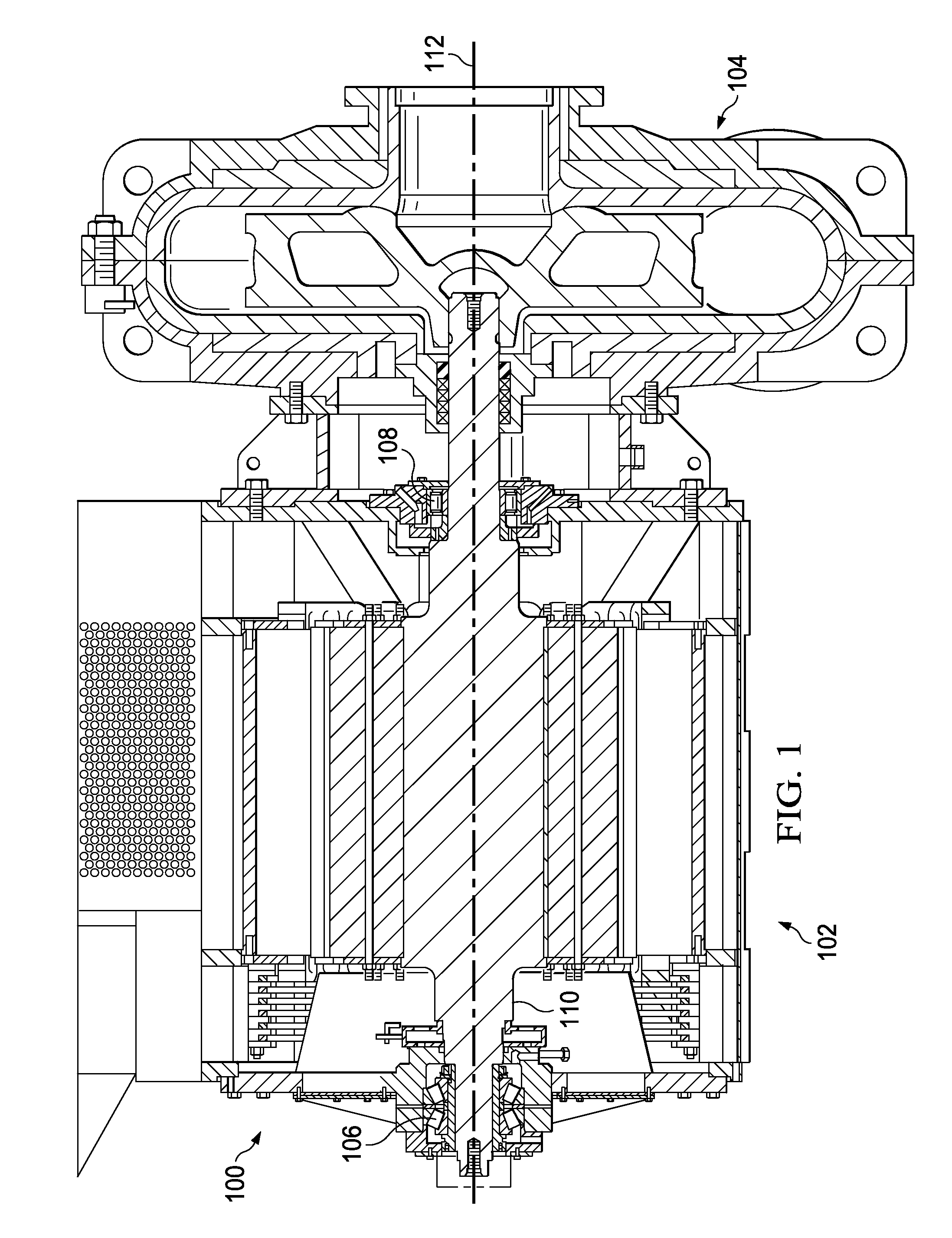
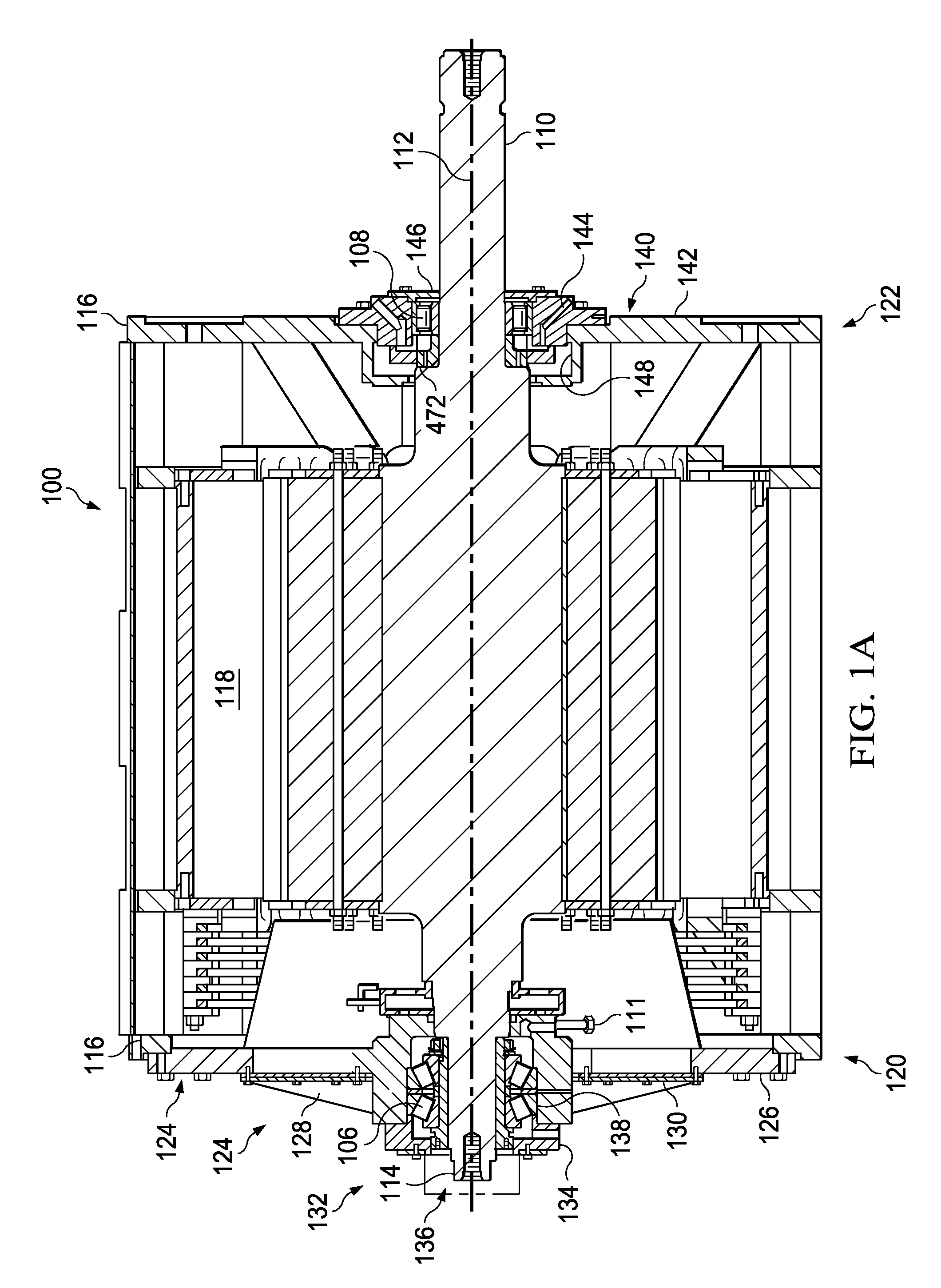
[0081]Referring to FIG. 1, an embodiment of a close-coupled pump 100 employing a power end 102, a fluid end 104 and a rotor shaft 110 extending between the power end 102 and the fluid end 104 is illustrated. The power end 102 has a first bearing assembly 106, oftentimes referred to as a dry end bearing assembly, and a second bearing assembly 108, oftentimes referred to as a wet end bearing assembly. Each of the bearing assemblies can also be referred to as sub-assemblies. The dry end bearing assembly 106 and the wet end bearing assembly 108 are both mounted on the rotor shaft 110, which rotates about a longitudinal axis 112. The close-coupled pump 100 is an illustrative, non-limiting example of how one or more bearing assemblies may be utilized and is not meant to infer a specific number or type of bearing assembly. While one skilled in the art will appreciate that bearings may be utilized in a number of different applications, the close-coupled pump 100 will be used as a backdrop f...


PUM

PropertyMeasurementUnit
thicknessaaaaaaaaaa
lengthaaaaaaaaaa
angleaaaaaaaaaa

Abstract

Apparatuses include an upper body and a lower body coupleable to the upper body for forming a channel to support a bearing assembly therein. A retention member extends into the channel from at least one of the upper body or the lower body. The retention member is configured to engage the bearing assembly to secure the bearing assembly within the channel. The apparatus further includes a lifting member formed in the upper body for receiving a hoisting member for lifting the bearing assembly.

Description

CROSS-REFERENCE TO RELATED APPLICATION[0001]This application claims priority to U.S. Provisional Patent Application No. 61 / 937,229 filed Feb. 7, 2014, which is incorporated herein by reference in its entirety.TECHNICAL FIELD[0002]This disclosure relates to bearing assemblies, and, in particular, to systems, apparatuses and methods for lifting, positioning and removing a bearing assembly from a shaft.BACKGROUND OF THE DISCLOSURE[0003]Bearings are used to reduce friction between and support moving parts, such as, for example, rotating shafts. Bearings have a finite operating life, requiring periodic replacement and routine maintenance to prevent failure. Several factors impact the service life of a bearing or the frequency for required maintenance. For example, bearing loads, operating temperature, exposure to external environments, contamination, lubrication and even electrical currents acting on the bearing may impact a bearing's service life or the frequency that maintenance must b...

Claims


Application Information

Patent Timeline
Patent Type & Authority Applications(United States)
IPC IPC(8): F16C35/06B66C1/62F16C35/04
CPCF16C35/062F16C35/042F16C2237/00F16C35/06B66C1/62F16C19/26F16C19/386Y10T29/49698Y10T29/53796Y10T29/53861Y10T29/53991
Inventor BOURGEOIS, RON J.KOSMICKI, RANDY J.VIKEN, MICHAEL L.
Owner WEIR SLURRY GRP INC
Why Eureka
Try Eureka