Microscope

a microscope and microscope technology, applied in the field of microscopes, can solve the problems of inability to integrate the methods of existing microscope systems, limited availability of commercial microscopes suitable for spim or lsfm, complex structure, etc., and achieve the effect of facilitating the integration of spim technology and facilitating the examination of small samples

Active Publication Date: 2015-08-13
CARL ZEISS MICROSCOPY GMBH
View PDF8 Cites 15 Cited by
  • Summary
  • Abstract
  • Description
  • Claims
  • Application Information

AI Technical Summary

Benefits of technology

[0020]Therefore, it is the object of the invention to further develop a microscope of the type described in the introductory part which facilitates integration of SPIM technology in existing microscopes, particularly which facilitates the examination of small samples, particularly by fluorescence spectroscopy methods.

Problems solved by technology

Heretofore, the availability of commercial microscopes suitable for SPIM or LSFM has been limited so that individual research groups generally developed their own creations.
This arrangement of sample chamber, detection beam path and illumination beam path in relation to one another leads to complex, large-sited structures, which is one of the reasons why there are still no commercially available microscopes for SPIM technology.
In particular, there has not yet been a commercial approach to integrate the methods in existing microscope systems.
However, none of the arrangements described above allows a simple, unproblematic integration in exiting microscopes.
But this arrangement also occupies a very large amount of space and is very costly because of the additional optics.

Method used


Image

  • Microscope
  • Microscope
  • Microscope

Examples


Embodiment Construction

[0039]It is to be understood that the figures and descriptions of the present invention have been simplified to illustrate elements that are relevant for a clear understanding of the present invention, while eliminating, for purposes of clarity, many other elements which are conventional in this art. Those of ordinary skill in the art will recognize that other elements are desirable for implementing the present invention. However, because such elements are well known in the art, and because they do not facilitate a better understanding of the present invention, a discussion of such elements is not provided herein.

[0040]The present invention will now be described in detail on the basis of exemplary embodiments.

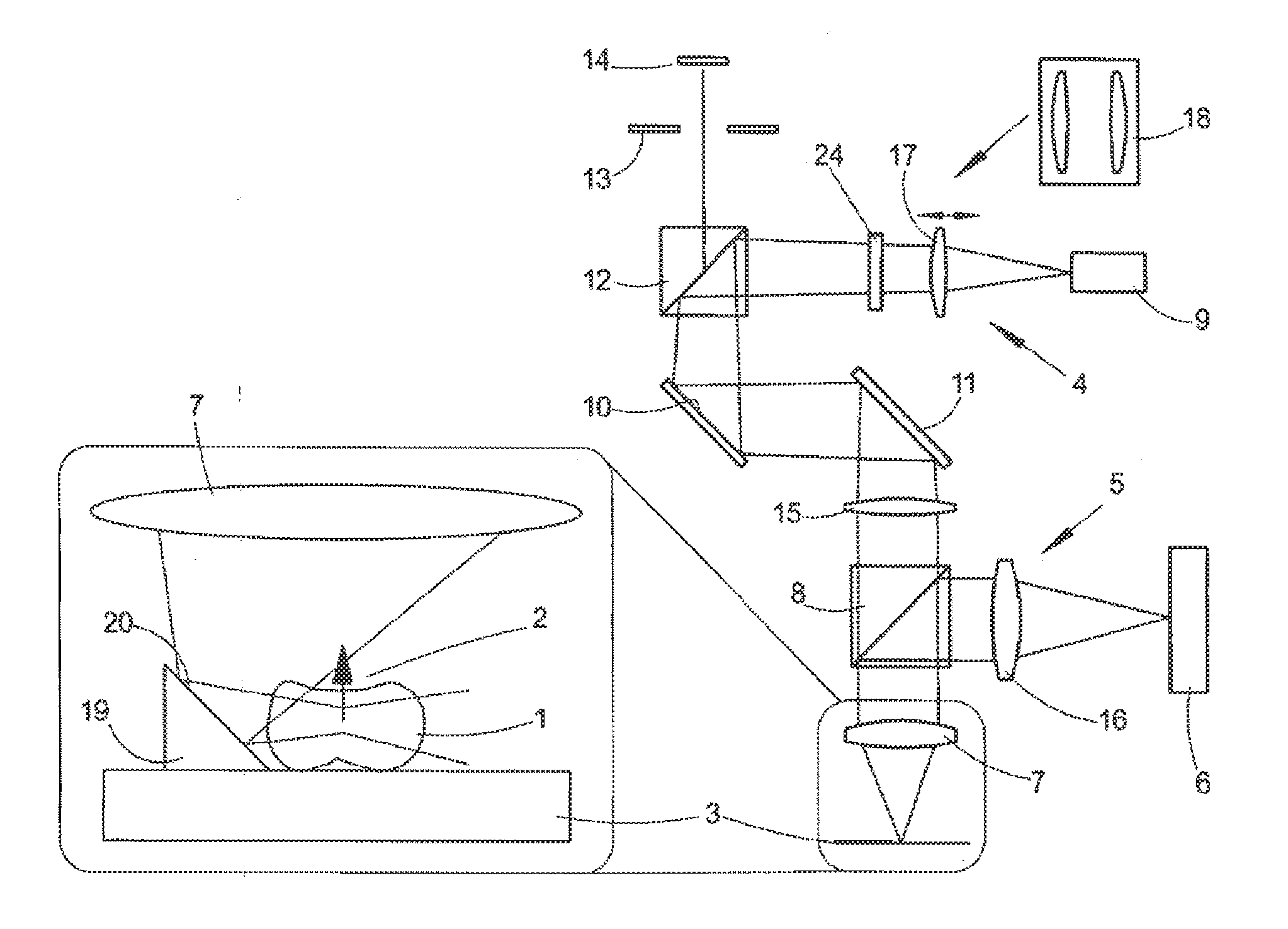
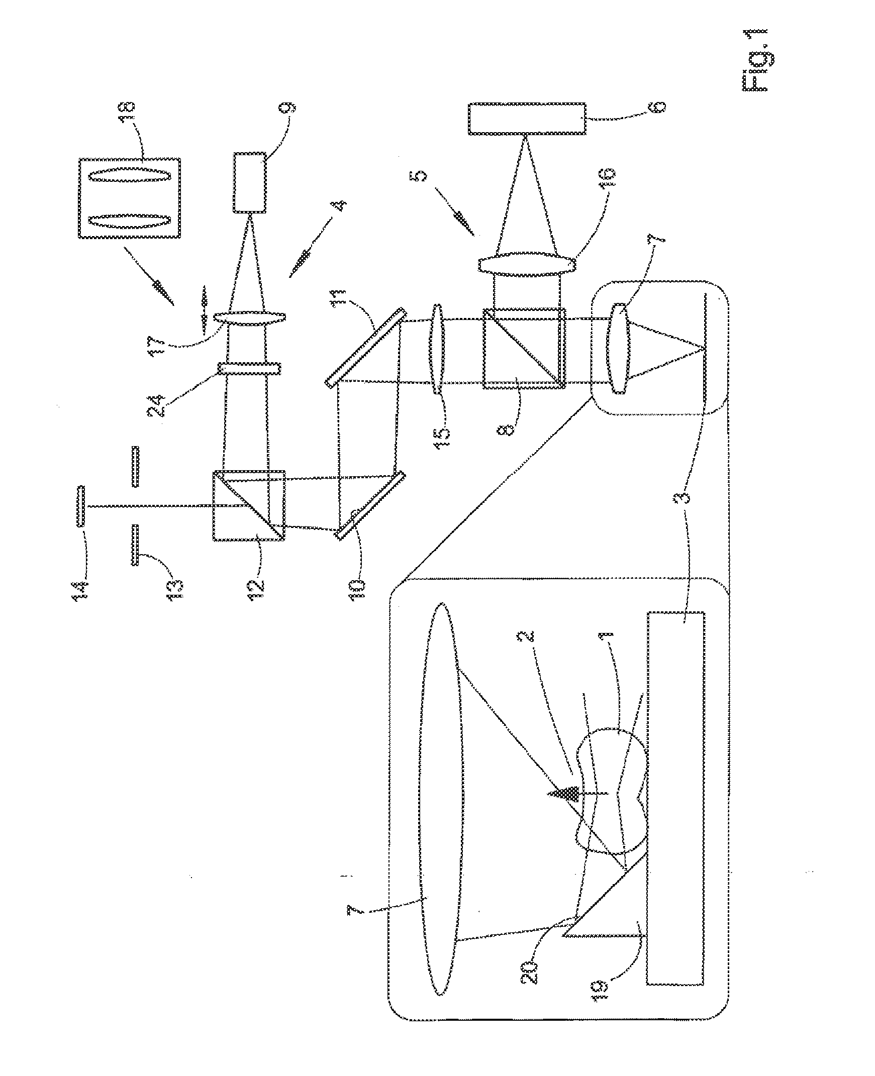
[0041]First, FIG. 1 shows the basic construction of a microscope with which a sample 1 can be irradiated with a light sheet perpendicular to the detection direction 2. A microscope of this type comprises a conventional sample stage with a stage surface in a stage plane perpendi...


PUM

PropertyMeasurementUnit
angleaaaaaaaaaa
angleaaaaaaaaaa
angleaaaaaaaaaa

Abstract

A microscope including a sample carrier configured to support a sample. Excitation light illuminates the sample via an excitation beam path, Detection light from the sample is guided to detection means via a detection beam oath. Through an objective arranged along the optical axis, excitation light is guided in direction of the sample carrier and detection light coming from the sample is guided in direction of the detection means. Beam-splitting means separate excitation light and detection light. Also provided are means for generating a light sheet from excitation tight, and means for illuminating the sample with this light sheet. The light sheet lies in a plane at a nonzero angle to the optical axis. The means for illuminating the sample include an optical-deflecting device arranged on or at the sample carrier, which deflects excitation light from the objective into the plane of the light sheet via an optically active surface.

Description

[0001]The present application claims priority from PCT Patent Application No. PCT / EP2013 / 061999 filed on Jun. 11, 2013, which claims priority from German Patent Application No. DE. 10 2012 211 943.4 tiled on Jul. 9, 2012, the disclosures of which are incorporated herein by reference in their entirety.1. FIELD OF THE INVENTION[0002]The invention is directed to a microscope. A microscope of this type comprises a sample stage with a stage surface in a stage plane that forms an angle different Chan zero to an optical axis Z. Arranged on the sample stage, preferably no as to be secured against unintentional displacement, is a sample carrier on which a sample is supported. The microscope further comprises an excitation beam path via which the sample is illuminated with excitation light and a detection beam path via which detection light coming from the sample is directed to detection means. The detection means comprise, for example, a camera or a pixel array or other recording equipment s...

Claims


Application Information

Patent Timeline
Patent Type & Authority Applications(United States)
IPC IPC(8): G01N21/64G02B21/16G02B21/26G02B21/00
CPCG01N21/6458G02B21/0032G02B21/16G01N2201/02G02B21/0048G01N2201/06113G02B21/26G02B21/06G02B21/367G01N2021/6463G02B21/0076G02B21/008
Inventor KLEPPE, INGOWOLLESCHENSKY, RALFLIPPERT, HELMUTKALKBRENNER, THOMAS
Owner CARL ZEISS MICROSCOPY GMBH
Why Eureka
Try Eureka