Image forming apparatus, and process cartridge
- Summary
- Abstract
- Description
- Claims
- Application Information
AI Technical Summary
Benefits of technology
Problems solved by technology
Method used
Image

Examples
embodiment 1
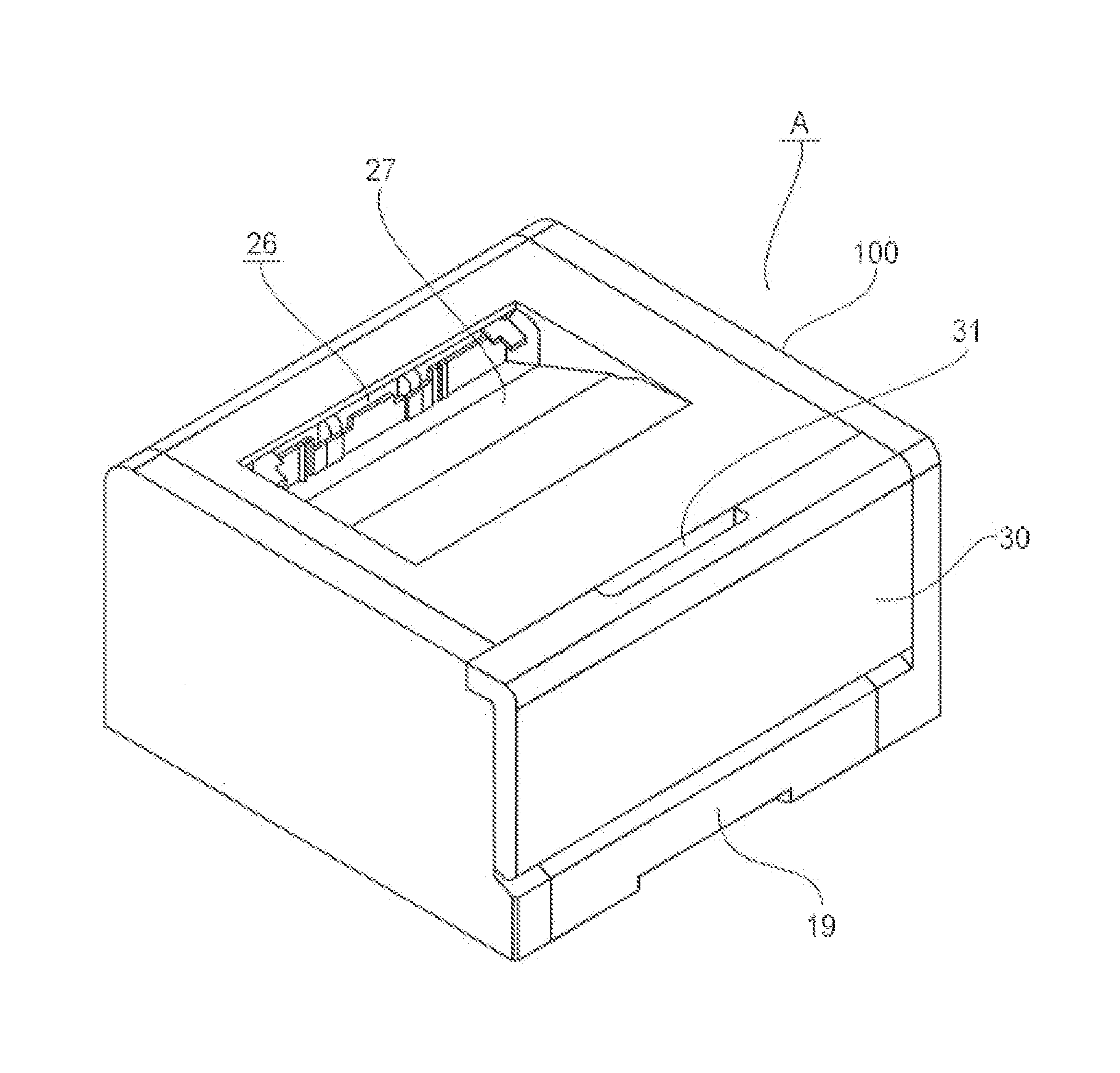
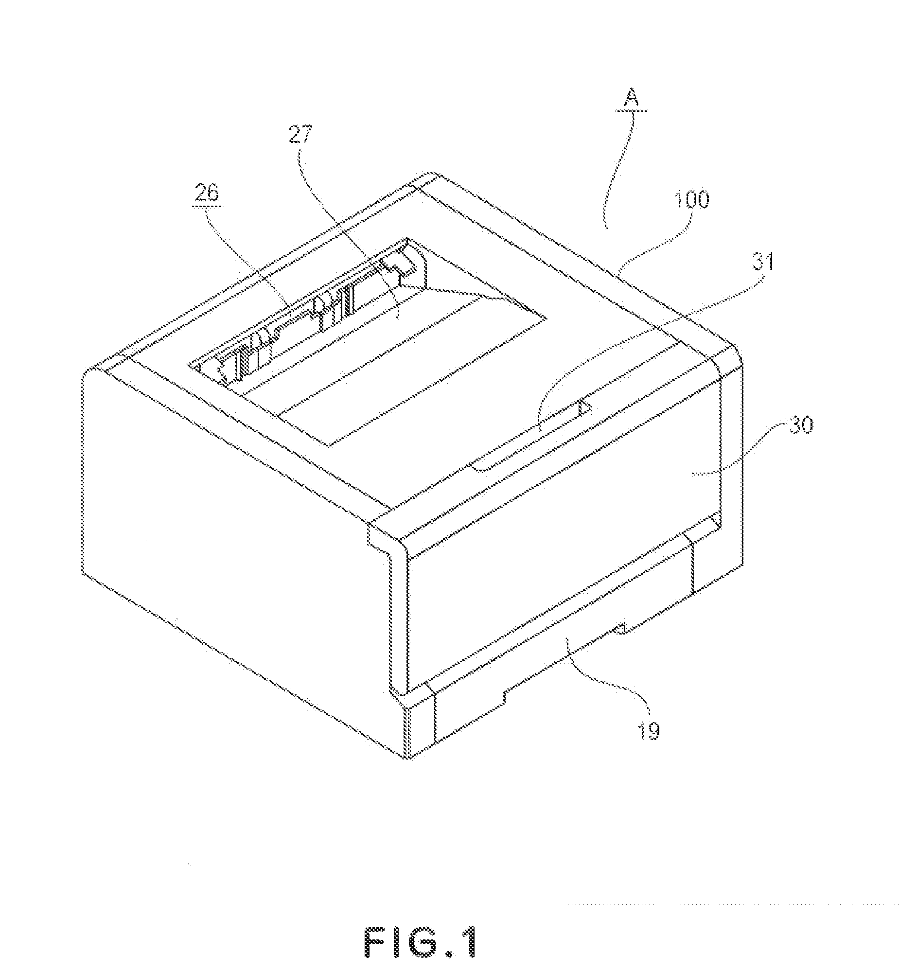
[0057]FIGS. 1-5 are drawings of the image forming apparatus A in this embodiment, which is a laser beam printer. First, the overall structure of this laser beam printer, and its functions, are described. Incidentally, in each of the following embodiments of the present invention, the image forming apparatus A is a full-color image forming apparatus in which four process cartridges are removably installable. However, the number of process cartridges installable in the image forming apparatus is not limited to tour. It is to be set as necessary.
[General Description of Image Forming Apparatus]
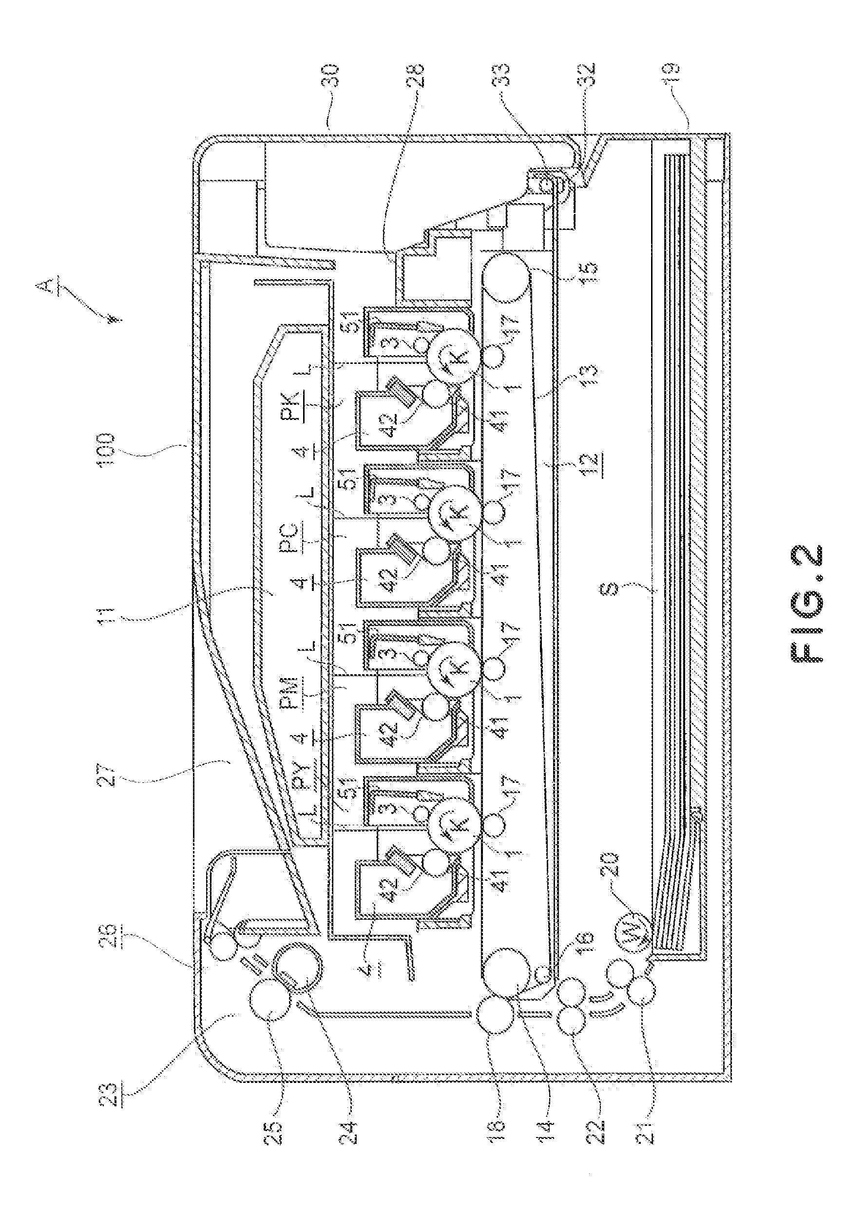
[0058]FIG. 2 is a sectional view of the image forming apparatus A in this embodiment. It shows the general structure of the apparatus A. There are disposed a laser scanner 11, an intermediary transfer belt 13, a fixation film 24, a pressure roller 25, a sheet feeder tray 19, a sheet feeder roller 20, etc., in the main assembly (which hereafter may be referred to simply apparatus main assembly) 100...
embodiment 2
[0130]This embodiment is a modification of the first embodiment in terms of the spacing member (engaging component) with which the development roller disengagement mechanism is provided. More specifically, the image forming apparatus in this embodiment is structured so that the spacing member 71 retracts by rotationally moving relative to the moving member 72. In the following description of this embodiment, description is centered around the sections of the image forming apparatus, which are different in structural arrangement from the counter parts of the image forming apparatus in the first embodiment; the portions of the image forming apparatus in this embodiment, which are similar to the counterparts of the image forming apparatus in the first embodiment are not described.
[0131]Referring to FIG. 17, the spacing member 71 is supported by the spacing member holder 72 so that it can be rotationally moved about the pressing member support shaft (pivot) 74 with which the moving memb...
embodiment 3
[0140]This embodiment is a modification of the first embodiment in terms of the spacing member (61), protrusion (44d), and force bearing surface (44b) of the development roller disengagement mechanism 60. The description of this embodiment will centered around the structural arrangement of the image forming apparatus in this embodiment, which is different from that in the first embodiment; the structural components and their function, which are same as the counterparts in the first embodiment will not be described.
[0141]Referring to FIG. 20, in this embodiment, the protrusion 44d is provided with a sub-protrusion and a recess 44g, which are for ensuring that the spacing member 61 engages with the force bearing surface 44b. The force bearing surface 44b is a part of the recess 44g of the protrusion 44d. The force bearing surface 44b and the protrusion contacting surface 61b of the spacing member 61 are lilted at a preset angle to ensure that the spacing member 61 engages with the pro...
PUM
 Abstract
Description
Claims
Application Information
 - Generate Ideas
- Intellectual Property
- Life Sciences
- Materials
- Tech Scout
- Unparalleled Data Quality
- Higher Quality Content
- 60% Fewer Hallucinations
Browse by: Latest US Patents, China's latest patents, Technical Efficacy Thesaurus, Application Domain, Technology Topic, Popular Technical Reports.
© 2025 PatSnap. All rights reserved.Legal|Privacy policy|Modern Slavery Act Transparency Statement|Sitemap|About US| Contact US: help@patsnap.com