Electrical contactor

a contactor and electric technology, applied in the field of electric contactors, can solve problems such as life-threatening electrical shock hazards, problems in multi-pole contactors, and unmetered electricity supplied, so as to reduce the deleterious effects of contact erosion, reduce erosion energy, and limit the damage of contact erosion energy available

Active Publication Date: 2015-08-13
JOHNSON ELECTRIC SA
View PDF45 Cites 3 Cited by
  • Summary
  • Abstract
  • Description
  • Claims
  • Application Information

AI Technical Summary

Benefits of technology

[0027]Direct DC driven or AC driven contactors can be conceived, and a feedback stabilized actuator can be attuned to the zero-crossing of the associated load waveform to reduce the deleterious effects of contact erosion due to arcing.
[0028]The AC drive pulse may preferably have a half-cycle waveform profile, so as to reduce erosion energy between the contacts. Alternatively and most preferably, the AC drive pulse may have a quarter-cycle waveform profile, so as to prevent contact separation prior to peak load current.
[0029]Preferably, the driving of one of the coils may induce an el

Problems solved by technology

In this welded-contact fault condition, un-metered electricity is supplied.
This can lead to a life-threatening electrical shock hazard, if the load connection that is thought to be disconnected is still live at 230 V AC

Method used


Image

  • Electrical contactor
  • Electrical contactor
  • Electrical contactor

Examples


Embodiment Construction

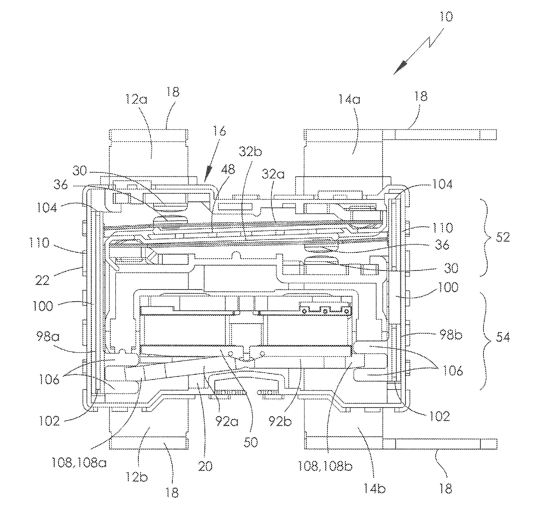
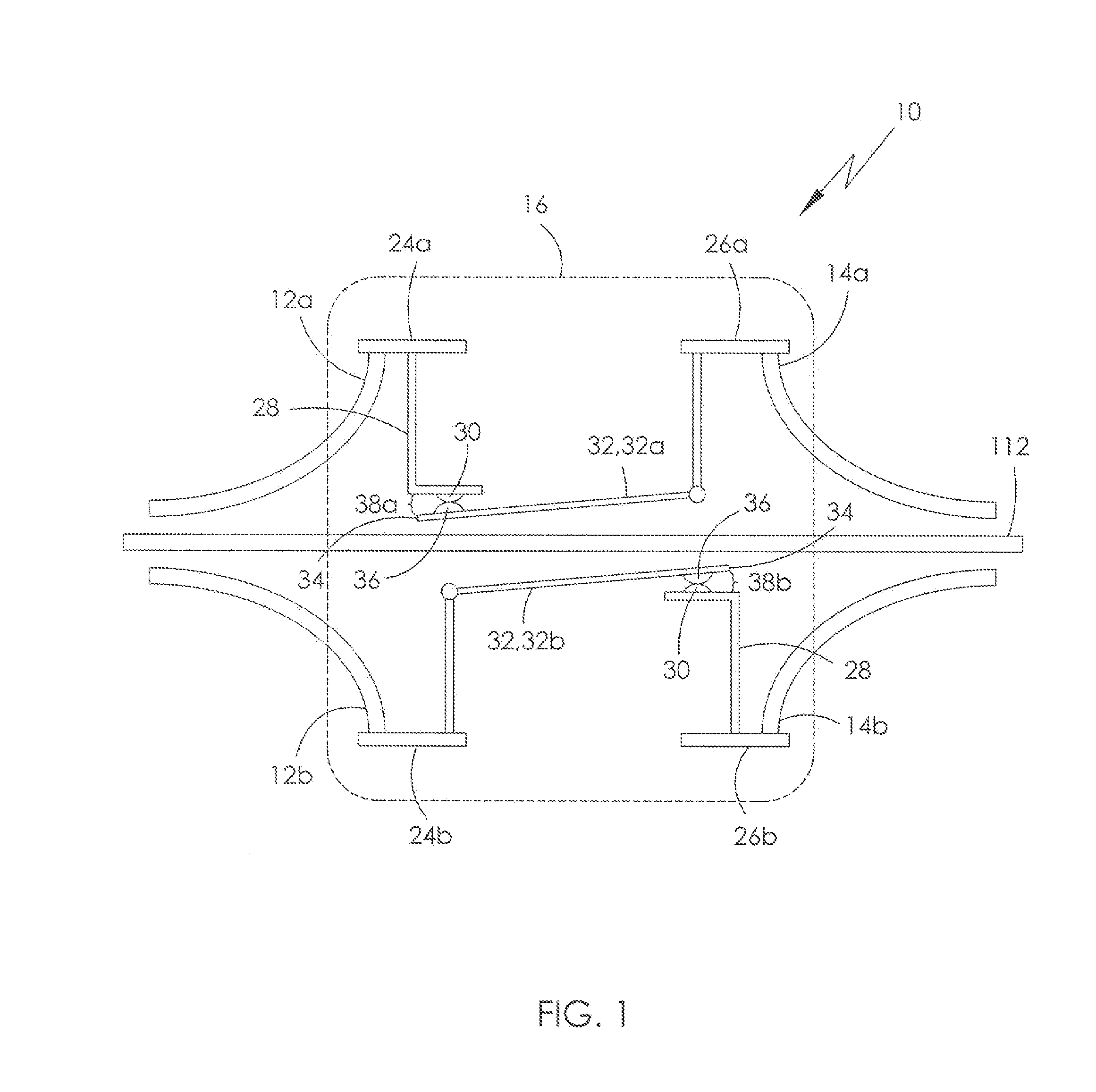
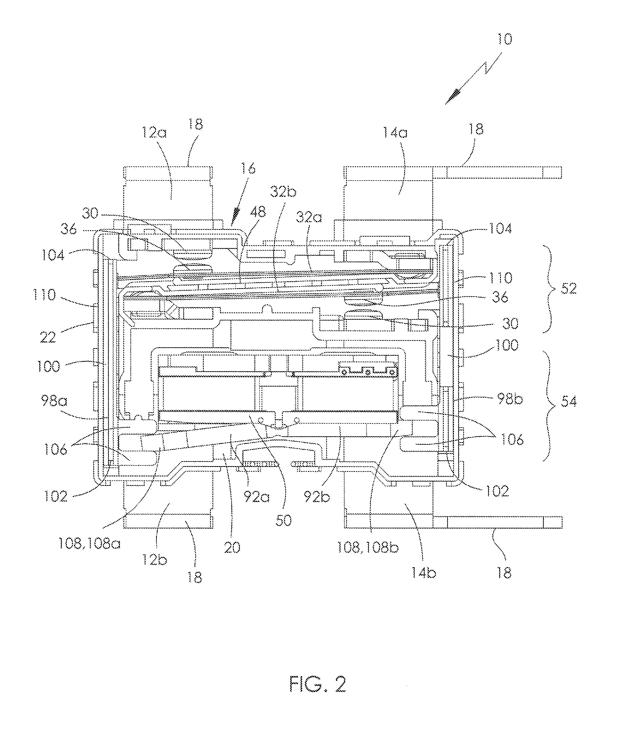
[0048]Referring firstly to FIGS. 1 to 4 of the drawings, there is shown a first embodiment of an electrical contactor, specifically but not necessarily exclusively a repulsion contactor, globally shown at 10 and in this case being a two-pole device. Although a two-pole device is described, the suggested improvements may be applicable to a single pole device or a device having more than two poles.

[0049]The contactor 10 includes first and second outlet terminals 12a, 12b and first and second feed terminals 14a, 14b. Each terminal 12a, 12b, 14a, 14b extends from a contactor housing 16, each terminating with a terminal stab 18, and is mounted to a housing base 20 and / or an upstanding perimeter wall 22 of the contactor housing 16. The housing cover is not shown for clarity.

[0050]The first outlet terminal 12a and the second feed terminal 14b respectively include first outlet and second feed terminals pads 24a, 26b, and from each extends a fixed, preferably electrically-conductive, member ...


PUM


Abstract

An electrical contactor has first and second terminals; a movable arm connected to the second terminal; and an actuator. The actuator has a magnet, first and second coils having a common connection and located either side of the magnet, a magnetic rocking armature pivotably attached between the coils and an actuation element connected to the first end of the rocking armature for actuating the movable arm. Driving the first coil causes a demagnetization of the first coil and a corresponding increase in magnetic flux in the second coil, latching the armature to the second coil and moving the movable arm in a first direction. Driving the second coil causes a demagnetization of the second coil and a corresponding increase in magnetic flux in the first coil, latching the rocking armature to the first coil and moving the movable arm in a second direction.

Description

CROSS REFERENCE TO RELATED APPLICATIONS[0001]This non-provisional patent application claims priority under 35 U.S.C. §119(a) from Patent Application No. GB1402560.5 filed in The United Kingdom on Feb. 13, 2014, the entire contents of which are hereby incorporated by reference.FIELD OF THE INVENTION[0002]This invention relates to an electrical contactor.BACKGROUND OF THE INVENTION[0003]The present invention relates to an electrical contactor, particularly but not necessarily exclusively for moderate AC switching contactors employed in modern electricity meters, so-called ‘smart meters’, for performing a load-disconnect function at normal domestic supply mains voltages, typically being 100 V AC to 250 V AC. The invention may also relate to an electrical contactor of a moderate, preferably alternating, current switch which may be subjected to a short-circuit fault condition requiring the contacts to not weld. In this welded-contact fault condition, un-metered electricity is supplied. T...

Claims


Application Information

Patent Timeline
IPC IPC(8): H01H36/00
CPCH01H36/008H01H50/16
Inventor CONNELL, RICHARD ANTHONY
Owner JOHNSON ELECTRIC SA
Why Eureka
Try Eureka