Methods and systems for removing and/or installing wind turbine rotor blades

a technology for installing rotor blades and wind turbines, which is applied in the field of wind turbines, can solve the problems of high cost of both transporting cranes to the wind turbine site and operating cranes, and currently accounts for a significant portion of the overall cost associated with initial wind turbine installation and rotor blade maintenance operations

Active Publication Date: 2015-08-20
GENERAL ELECTRIC CO
View PDF4 Cites 45 Cited by
  • Summary
  • Abstract
  • Description
  • Claims
  • Application Information

AI Technical Summary

Benefits of technology

In one aspect, the present subject matter is directed to a method for removing a rotor blade from a wind turbine. The method may generally include installing a blade sock around an outer perimeter of the rotor blade at an intermediate location defined between a blade root and a blade tip of the rotor blade and coupling a support cable to the blade root. The support cable may extend from the blade root and into a hub of the wind turbine. In addition, the method may include lowering the rotor blade relative to the hub using the support cable such that the rotor blade is spaced apart from the hub by an initial vertical distance, coupling at least one pulley cable between the rotor blade and a winch located on or adjacent to a support surface of the wind turbine using at least one pulley, moving the at least one pulley cable relative to the at least one pulley to lower the rotor blade relative to the hub beyond the initial vertical distance, applying a force through the blade sock as the at least one pulley cable is moved relative to the at least one pulley in order to control an orientation of the rotor blade relative to at least one of a tower of the wind turbine or the support surface and further lowering the rotor blade to a location on or adjacent to the support surface.
In another aspect, the present subject matter is directed to a method for lowering a rotor blade relative to a hub of a wind turbine, wherein the wind turbine includes a pitch bearing coupled to the hub. The method may generally include installing a plurality of cable translation devices within the hub, wherein each of the plurality of cable translation devices comprises a cable hoist. The method may also include inserting a plurality of support nuts at least partially through a blade root of the rotor blade, installing a plurality of support cables in operative association with the plurality of cable translation devices, coupling each of the support cables to one of the support nuts and operating the cable translation devices such that the support cables are moved relative the cable translation devices in a manner that causes the rotor blade to be lowered relative to the hub.
In a further aspect, the present subject matter is directed to a system for lowering a rotor blade relative to a hub of a wind turbine, wherein the wind turbine includes a pitch bearing coupled to the hub. The system may generally include a plurality of cable translation devices configured to be positioned within the hub and a plurality of support nuts configured to be installed at least partially through a blade root of the rotor blade. In addition, the system may include a plurality of support cables, with each support cable being configured to be placed in operative association with one of the cable translation device and being coupled to one of the support nuts. The cable translation devices may be configured to be operated such that the support cables are moved relative the cable translation devices in a manner that causes the rotor blade to be lowered relative to the hub.

Problems solved by technology

Unfortunately, it is often extremely expensive to both transport the crane to the wind turbine site and operate the crane for the amount of time necessary to install and / or remove the rotor blade(s).
As a result, the costs of employing such large cranes currently accounts for a significant portion of the overall costs associated with initial wind turbine installations and rotor blade maintenance operations.

Method used


Image

  • Methods and systems for removing and/or installing wind turbine rotor blades
  • Methods and systems for removing and/or installing wind turbine rotor blades
  • Methods and systems for removing and/or installing wind turbine rotor blades

Examples


Embodiment Construction

Reference now will be made in detail to embodiments of the invention, one or more examples of which are illustrated in the drawings. Each example is provided by way of explanation of the invention, not limitation of the invention. In fact, it will be apparent to those skilled in the art that various modifications and variations can be made in the present invention without departing from the scope or spirit of the invention. For instance, features illustrated or described as part of one embodiment can be used with another embodiment to yield a still further embodiment. Thus, it is intended that the present invention covers such modifications and variations as come within the scope of the appended claims and their equivalents.

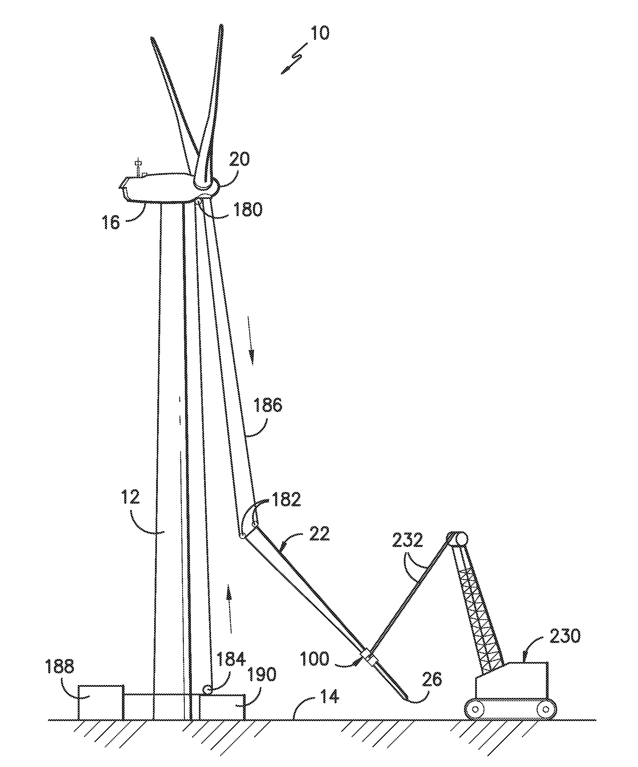
In general, the present subject matter is directed to various methods for removing rotor blades from and / or installing rotor blades onto a wind turbine. Specifically, as will become apparent from the description provided below, the disclosed methods may allow for...


PUM


Abstract

A method for removing a rotor blade from a wind turbine may generally include installing a blade sock around an outer perimeter of the rotor blade, coupling a support cable to the blade root, lowering the rotor blade relative to the hub using the support cable, coupling at least one pulley cable between the rotor blade and a winch using at least one pulley, moving the pulley cable relative to the pulley to lower the rotor blade relative to the hub, applying a force through the blade sock as the pulley cable is moved relative to the pulley in order to control an orientation of the rotor blade and further lowering the rotor blade to a location on or adjacent to the support surface.

Description

FIELD OF THE INVENTIONThe present subject matter relates generally to wind turbines and, more particularly, to an improved methods and systems for removing and / or installing the rotor blades of a wind turbine.BACKGROUND OF THE INVENTIONWind power is considered one of the cleanest, most environmentally friendly energy sources presently available, and wind turbines have gained increased attention in this regard. A modern wind turbine typically includes a tower, generator, gearbox, nacelle, and one or more rotor blades. The rotor blades capture kinetic energy of wind using known foil principles. The rotor blades transmit the kinetic energy in the form of rotational energy so as to turn a shaft coupling the rotor blades to a gearbox, or if a gearbox is not used, directly to the generator. The generator then converts the mechanical energy to electrical energy. A power converter typically regulates the flow of electrical power between the generator and a grid.Typically, to initially insta...

Claims


Application Information

Patent Timeline
Patent Type & Authority Applications(United States)
IPC IPC(8): B66D1/60B66D1/36
CPCB66C1/108B66C1/66B66C13/08F05B2230/61F05B2230/70F03D80/50Y02E10/72Y02P70/50B66D1/36B66D1/60
Inventor HOLLOWAY, BRENT HAMILTONNEUMANN, ULRICH WERNERPFEIFFER, GAYLON MITCHELLJOHNSON, MICHAEL R.HACH, FORREST CHRISTOPHERCOSTAIN, KEVIN
Owner GENERAL ELECTRIC CO
Why Eureka
Try Eureka