Pneumatic wheel lift synchronization

a pneumatic wheel and lift technology, applied in the field of vehicle lifts, can solve the problems of a single-acting gravity return cylinder in the pneumatic lift system, a great disparity in the forces required to overcome static and dynamic friction, and a more “ratcheting” motion of the lift, so as to solve the problem of smooth system of the application

Active Publication Date: 2015-08-20
GRAY MFG
View PDF22 Cites 49 Cited by
  • Summary
  • Abstract
  • Description
  • Claims
  • Application Information

AI Technical Summary

Problems solved by technology

However, single-acting gravity return cylinders in pneumatic lift systems have suffered from a great disparity in the forces required to overcome static and dynamic friction, as compared to their hydraulic and mechanical counterparts.
The compressible nature of air results in the inability to obtain small and precise adjustments in order to maintain the smooth synchronization of lifts, resulting in more of a “ratcheting” motion of the lifts.
Although the lift system of the '812 application represents a significant advancement in automobile wheel lifts, the system of said application does not solve the problem of smoothly overcoming static and dynamic friction in pneumatic lift systems.

Method used


Image

  • Pneumatic wheel lift synchronization
  • Pneumatic wheel lift synchronization
  • Pneumatic wheel lift synchronization

Examples


Embodiment Construction

The following detailed description of various embodiments of the present technology references the accompanying drawings which illustrate specific embodiments in which the technology can be practiced. The embodiments are intended to describe aspects of the technology in sufficient detail to enable those skilled in the art to practice them. Other embodiments can be utilized and changes can be made without departing from the scope of the technology. The following detailed description is, therefore, not to be taken in a limiting sense. The scope of the present technology is defined only by the appended claims, along with the full scope of equivalents to which such claims are entitled.

Note that in this description, references to “one embodiment” or “an embodiment” mean that the feature being referred to is included in at least one embodiment of the present invention. Further, separate references to “one embodiment” or “an embodiment” in this description do not necessarily refer to the s...


PUM


Abstract

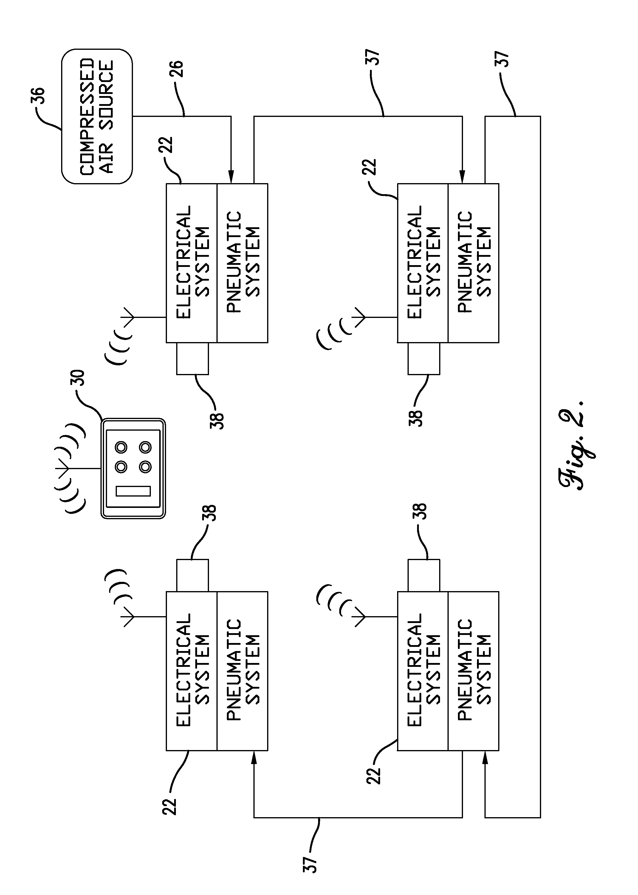
A self-synchronizing wheel lift system configured to lift a vehicle using compressed air. The lift system comprises a plurality of pneumatic wheel lifts and a lift control system. The lift control system is configured to automatically synchronize the heights of the wheel lifts during vehicle lifting without causing any of the wheel lifts to completely stop during vehicle lifting.

Description

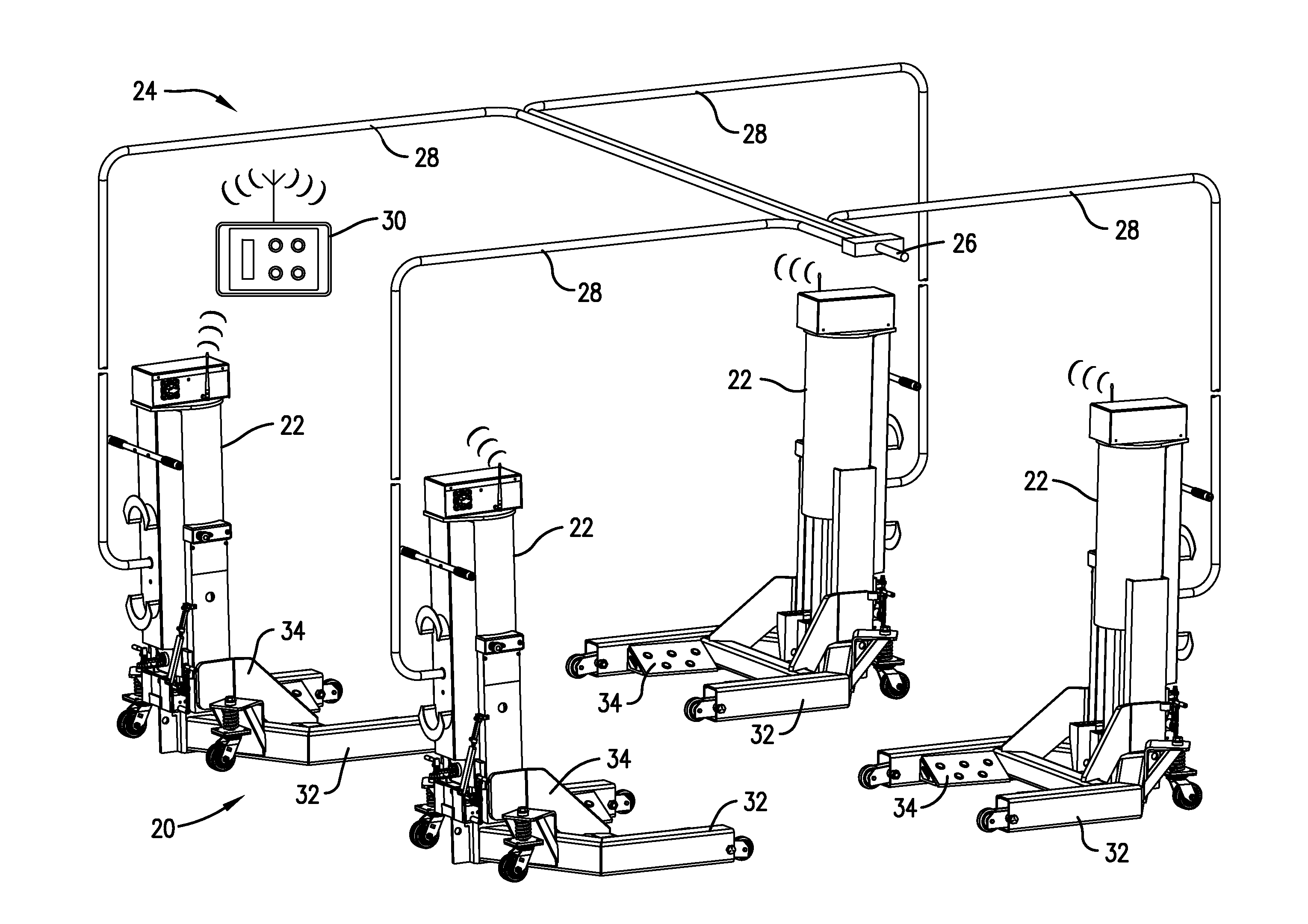
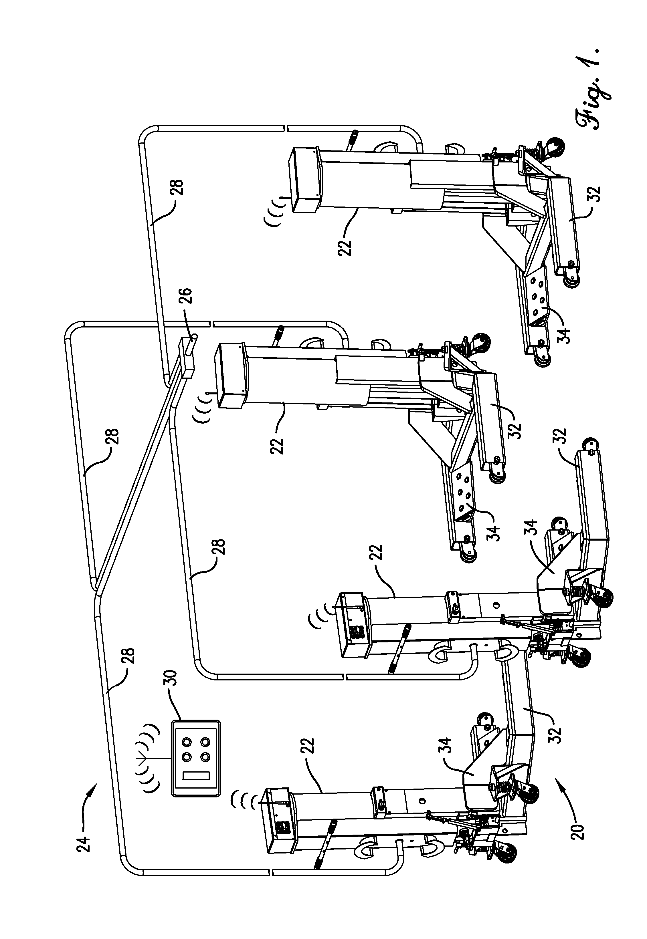
FIELD OF THE INVENTIONThe present invention relates generally to vehicle lifts. More particularly, certain embodiments of the present invention relate to pneumatically powered vehicle lifts that employ a pulse width modulated control system for precisely synchronizing pneumatic lifts and avoiding static friction.BACKGROUNDThe maintenance of vehicles such as cars and trucks frequently requires access to the underside of the vehicles in order to permit repair of such parts as transmissions, clutches, gearing, joints, brakes, and the like. In order to reach these areas of a vehicle, a worker will typically employ one or more lifting devices that are positioned beneath the vehicle chassis or wheels and actuated to lift the vehicle above the ground.Conventional lifting systems comprising a plurality of lifting devices may be powered by hydraulic or mechanical systems, which allow for a smooth raising and lowering motion throughout the range of travel as a result of small differences in s...

Claims


Application Information

Patent Timeline
Patent Type & Authority Applications(United States)
IPC IPC(8): B66F3/46B66F3/24B66F5/04
CPCB66F3/46B66F3/247B66F5/04B66F7/04
Inventor JAIPAUL, LARRY M.HELMICH, SETH A.
Owner GRAY MFG
Why Eureka
Try Eureka