Borehole inspecting and testing device and method of using the same

a technology of borehole and inspection device, which is applied in the direction of borehole/well accessories, survey, construction, etc., can solve the problems of saving significant amounts of money in the overall cost of the pile, and achieve the effects of saving more money, increasing the design load, and reducing the safety margin

Inactive Publication Date: 2015-08-20
PILE DYNAMICS
View PDF12 Cites 22 Cited by
  • Summary
  • Abstract
  • Description
  • Claims
  • Application Information

AI Technical Summary

Benefits of technology

[0018]According to a further aspect of the invention of this application, the device can measure one or more conditions of the side of the borehole wherein the designer can with more confidence design for bearing capacities and thus potentially save more money by justifiably reducing the safety margin (by either decreasing the assumed ultimate bearing capacity or increasing the design load since in either case the actual capacity is then better known).
[0019]According to even yet another aspect of the invention of this application, the device can use the weight of the drilling equipment as a reaction load. In fact, the device is conceived in such a wa

Problems solved by technology

By using the device of this application, designers can with more confidence include end bearing in

Method used


Image

  • Borehole inspecting and testing device and method of using the same
  • Borehole inspecting and testing device and method of using the same
  • Borehole inspecting and testing device and method of using the same

Examples


Embodiment Construction

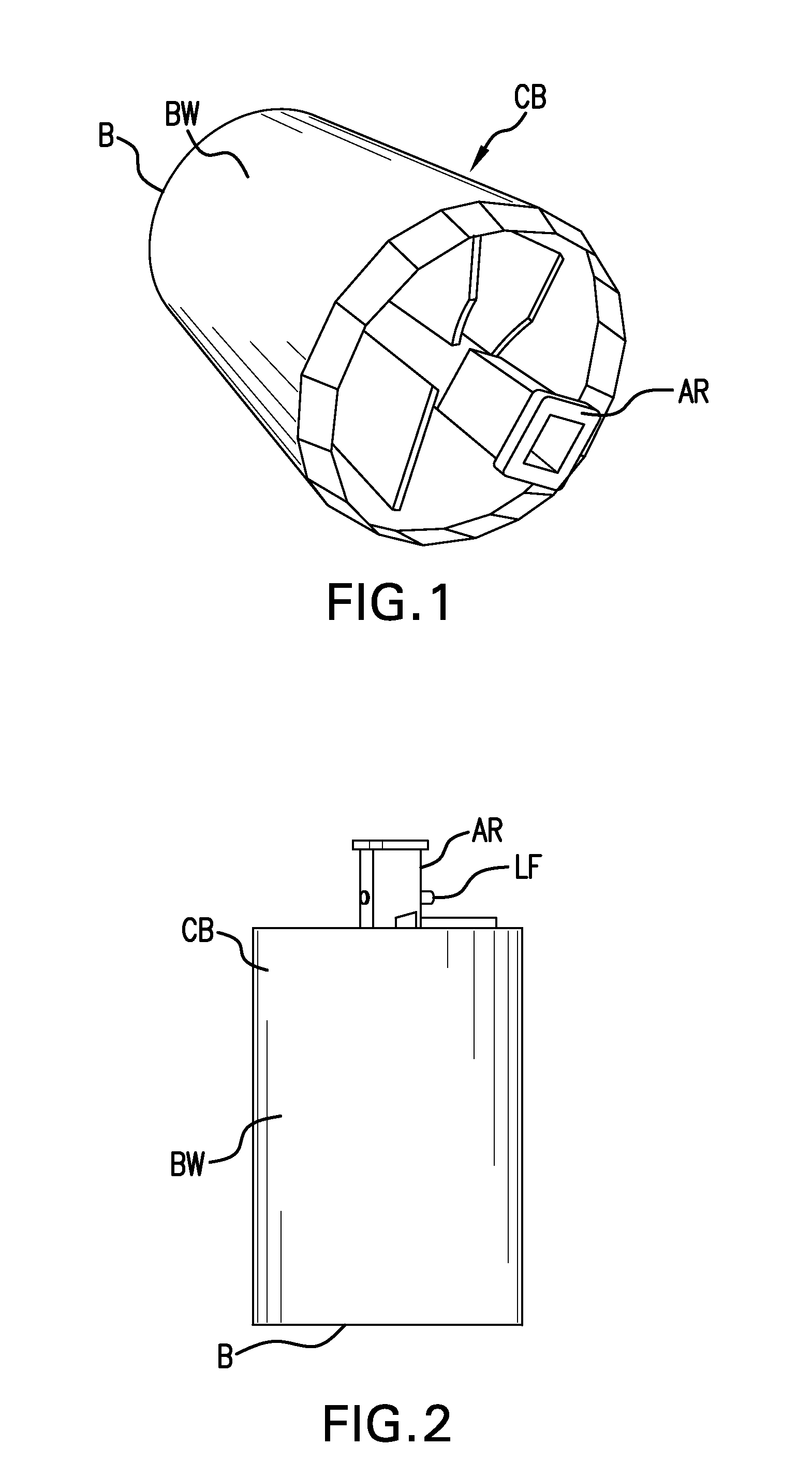
[0049]Referring now to the drawings wherein the showings are for the purpose of illustrating preferred and alternative embodiments of the invention only and not for the purpose of limiting the same, FIGS. 1 and 2 show a prior art clean out bucket CB which includes a mounting arrangement AR configured to selectively secure the bucket to a drilling mast, drillstem or Kelly bar (not shown in these figures). These masts have a square cross-sectional configuration wherein the mounting arrangement can be sized to slide over the mast and includes a locking features LF to secure the bucket relative to the mast. However, any attachment configuration could be used without detracting from the invention of this application. By including a square configuration, the mast can impart a rotational force on the bucket. The bucket further includes one or more side walls BW and a bottom B having a blade and a blade opening (both not shown). In operation the bucket is rotated such that the blade directs...


PUM


Abstract

A borehole inspection device and method of using the same to measure the condition of the bottom extent of a borehole, the system having a head unit assembly with top and bottom sides and including at least one downwardly extending force sensor configured to measure a reaction force applied to the at least one sensor as it engages a bottom extent of the borehole, the inspection device being configured to be lowered into a borehole and to bring the sensor(s) into contact with the bottom extent wherein continued downward movement of the head unit creates the reaction force on the sensor(s) to determine at least one of a location of an associated debris layer, a bearing capacity of the associated debris layer, the thickness of the associated debris layer, the location of an associated bearing layer and/or the bearing capacity of the associated bearing layer.

Description

[0001]This application claims priority in provisional patent applications Ser. No. 61 / 912,206 that was filed on Dec. 5, 2013, which is incorporated by reference herein.[0002]The invention of this application relates to a borehole measuring device. More particularly, the invention of this application relates to a measuring device that can be deployed in a borehole to inspect the borehole, in particular, to inspect the shaft bottom and / or side walls of the borehole and provide fast and reliable information about the quality and bearing capacity of the soils in the borehole.INCORPORATION BY REFERENCE[0003]McVay et al.—U.S. Pat. No. 6,533,502 discloses a wireless apparatus and method for analysis of piles which is incorporated by reference herein for showing the same. In addition, Mullins et al.—U.S. Pat. No. 6,783,273 discloses a method for testing integrity of concrete shafts which is also incorporated by reference in this application for showing the same. Piscsalko et al.—U.S. Pat. N...

Claims


Application Information

Patent Timeline
IPC IPC(8): E21B47/00E21B47/09E21B47/04E21B47/06
CPCE02D1/02
Inventor LIKINS, JR., GARLAND E.PISCSALKO, GEORGE R.FRANK RAUSCHE, FRANKCOTTON, DEAN A.
Owner PILE DYNAMICS
Why Eureka
Try Eureka