Method and a device for determining the wind speed to be taken into account in order to optimize the takeoff weight of an aircraft

a technology of wind speed and takeoff weight, applied in the direction of traffic control systems, transportation and packaging, instruments, etc., can solve the problems of increasing the power the aircraft needs to deliver, increasing the air speed, and increasing the aerodynamic drag on the aircraft, so as to improve the performance of the aircraft on takeoff and improve the payload. , the effect of reducing the safety margin

Active Publication Date: 2017-08-08
EUROCOPTER
View PDF10 Cites 1 Cited by
  • Summary
  • Abstract
  • Description
  • Claims
  • Application Information

AI Technical Summary

Benefits of technology

[0034]An object of the present invention is thus to propose a method and a device making it possible to overcome the above-mentioned limitations, thereby reducing the safety margin used in order to determine the maximum authorized takeoff weight of the aircraft depending on the speed of head wind to which the aircraft is subjected while taking off. The invention seeks to determine this speed of the head wind to which the aircraft is really subjected in a manner that is accurate and of integrity, and to take it into account so as to optimize the maximum authorized takeoff weight of the aircraft, thereby improving the performance of the aircraft on takeoff and in particular improving its payload without degrading the safety in flight of the aircraft.

Problems solved by technology

This increase in air speed gives rise in particular to an increase in the aerodynamic drag to which the aircraft is subjected, thus requiring an increase in the power the aircraft needs to deliver.
Nevertheless, the air speed supplied by a conventional air data computer is not always accurate and reliable.
That type of instrument is not capable of measuring wind speeds that are low of less than 30 knots (kt), with good stability and good accuracy.
Furthermore, that type of instrument measures air speed in one direction only, such that the measurements for the magnitude and the direction of the wind when the aircraft is stationary on the ground can be inaccurate.
Consequently, each main rotor and possibly a tail rotor produce respective washes resulting from their own rotation that can disturb the air stream surrounding the aircraft in the vicinity of its air pressure inlets.
Consequently, measurements provided by conventional air data computers on board a rotary wing aircraft do not generally make it possible to obtain a measurement of wind speed that is accurate and of integrity, when the aircraft is stationary on the ground.

Method used


Image

  • Method and a device for determining the wind speed to be taken into account in order to optimize the takeoff weight of an aircraft
  • Method and a device for determining the wind speed to be taken into account in order to optimize the takeoff weight of an aircraft

Examples


Embodiment Construction

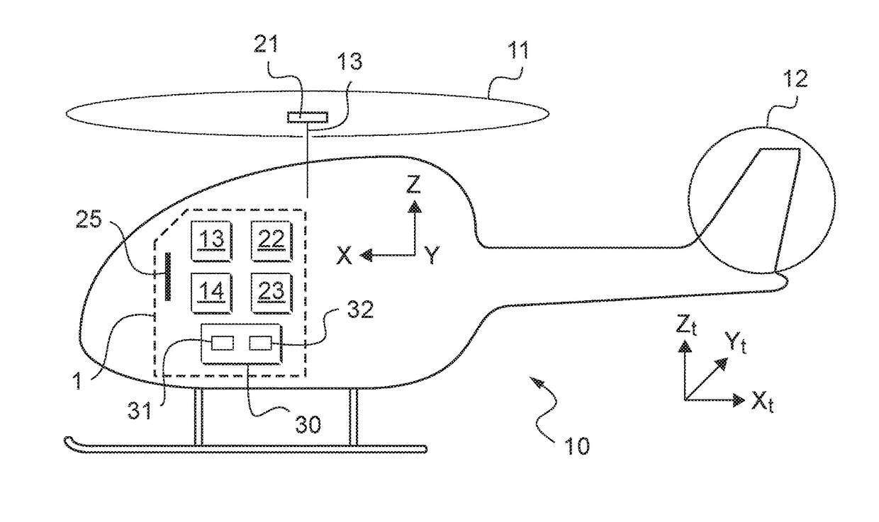
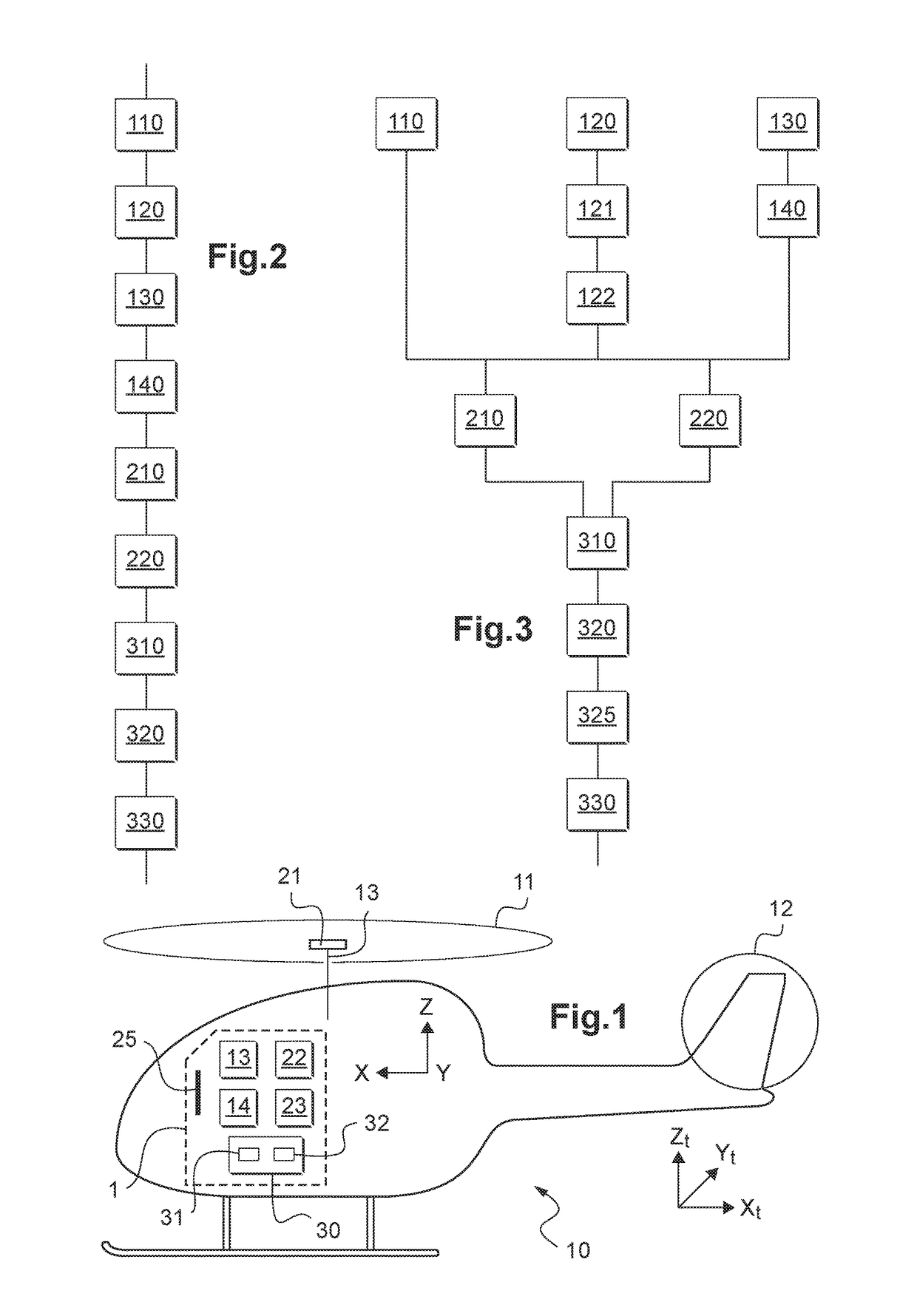
[0160]In FIG. 1, there can be seen an aircraft 10 that has a main rotor 11 located above a fuselage and an anti-torque tail rotor 12 that is positioned at the rear end of a tail boom.

[0161]A local reference frame (X, Y, Z) is associated with the aircraft 10, and more particularly with its center of gravity. The longitudinally extending direction of the aircraft 10 corresponds to the axis X and extends from the front of the aircraft 10 towards the rear of the aircraft 10. A vertically extending direction of the aircraft 10 corresponds to the axis Z and extends upwards perpendicularly to the longitudinal direction X. Finally, a transversely extending direction of the aircraft 10 corresponds to the axis Y and extends from right to left perpendicularly to the longitudinal direction X and the direction in elevation Z.

[0162]The longitudinal direction X is the roll axis of the aircraft 10, the transverse direction Y is its pitching axis, and the direction in elevation Z is its yaw axis.

[01...


PUM


Abstract

A method of determining the speed of the wind to be taken into account for determining a maximum authorized takeoff weight of an aircraft. A measured speed TASmes of the local wind is calculated from at least one current speed TASinst of the local wind and an observed speed TASobs of the local wind on the basis of weather observations and on the basis of a heading value. The measured speed TASmes is compared with the observed speed TASobs in order to determine a calculated speed TASperfo of the local wind while also making use of at least one instability criterion of the local wind as supplied by the weather observations and weather forecasts. The calculated speed TASperfo is then for taking into account in order to optimize the maximize authorized takeoff weight of the aircraft.

Description

CROSS REFERENCE TO RELATED APPLICATION[0001]This application claims priority to French patent application No. FR 15 00077 filed on Jan. 15, 2015, the disclosure of which is incorporated in its entirety by reference herein.BACKGROUND OF THE INVENTION[0002](1) Field of the Invention[0003]The present invention lies in the field of optimizing the performance of an aircraft, and more particularly of a rotary wing aircraft on takeoff.[0004]The present invention relates to a method of determining the wind speed to be taken into account in order to optimize the takeoff weight of an aircraft, and also to a device for performing the method.[0005](2) Description of Related Art[0006]The ability to optimize the performance of an aircraft is a crucial element for operators of any aircraft. The performance of an aircraft is strongly influenced by the speed of the aircraft relative to the surrounding air. For convenience, the term “air speed” is used below to designate the speed of an aircraft rela...

Claims


Application Information

Patent Timeline
Patent Type & Authority Patents(United States)
IPC IPC(8): G08G5/00B64D43/02B64C27/04G01P5/26G01P21/02
CPCG08G5/0065B64C27/04B64D43/02G01P5/26G01P21/025G08G5/0091G01P5/00
Inventor POUDRAI, ETIENNECERTAIN, NICOLASSPINOSI, BERNARD
Owner EUROCOPTER
Why Eureka
Try Eureka