Turbine assembly
- Summary
- Abstract
- Description
- Claims
- Application Information
AI Technical Summary
Benefits of technology
Problems solved by technology
Method used
Image

Examples
Embodiment Construction
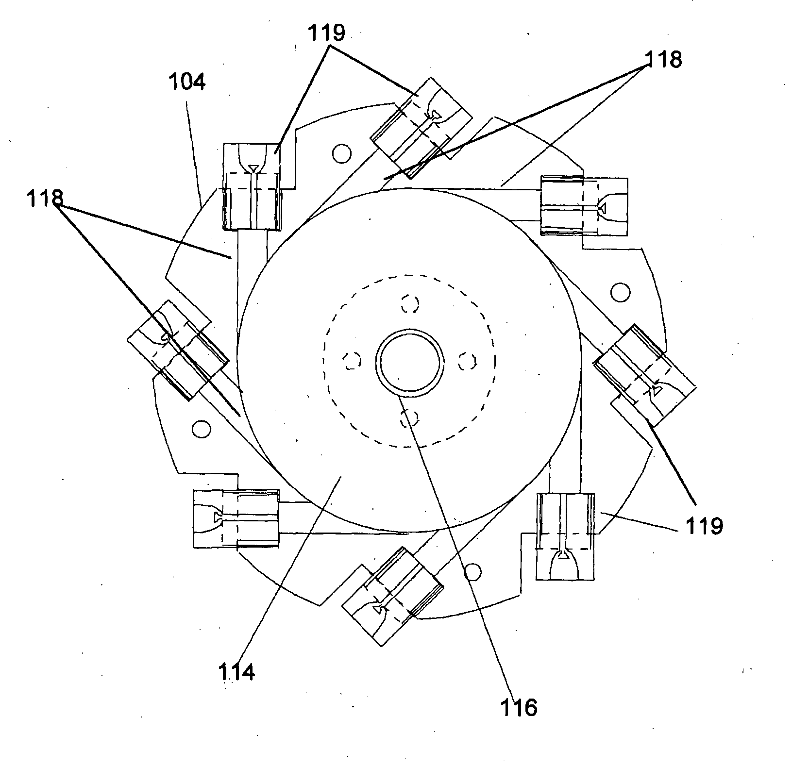
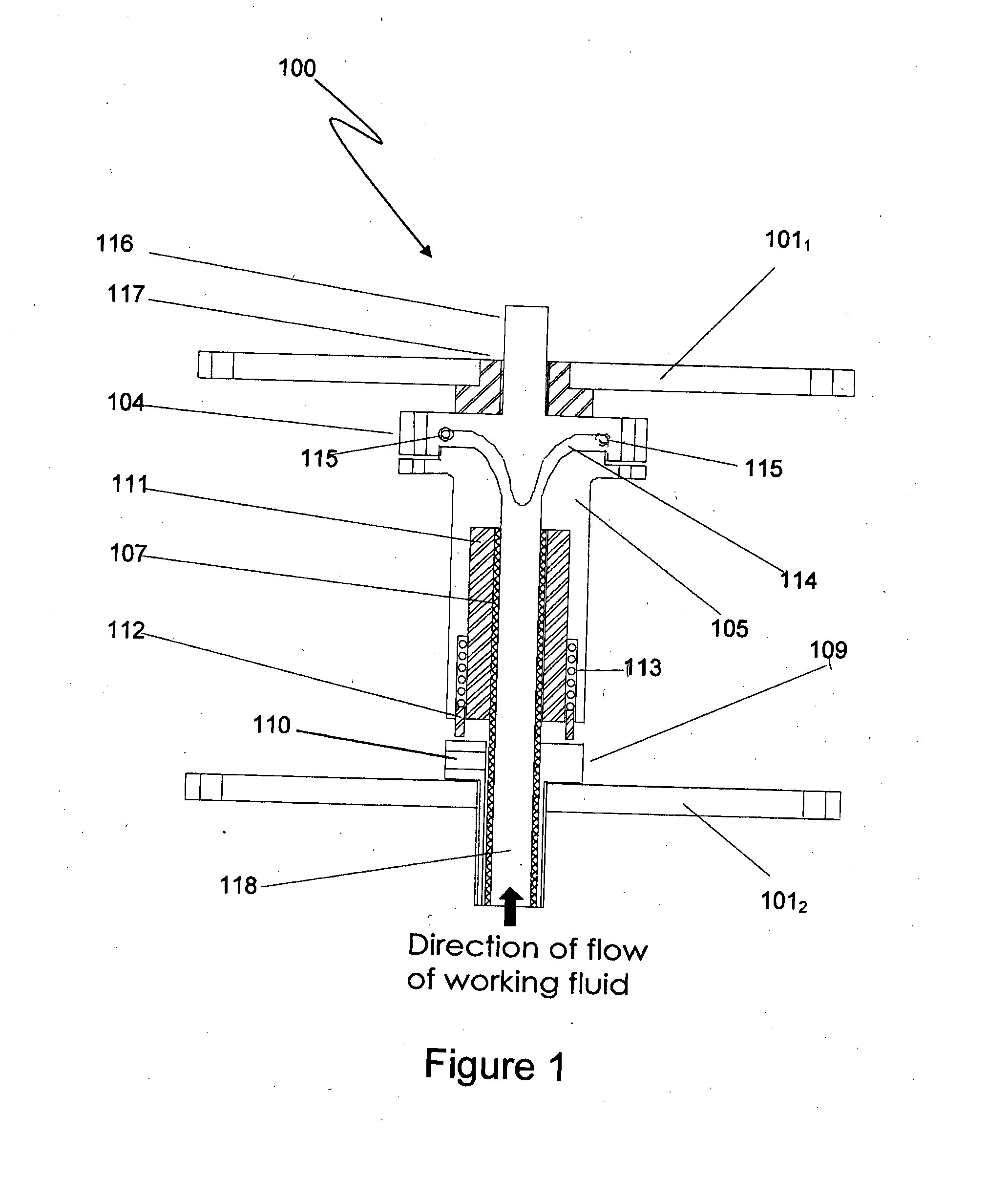
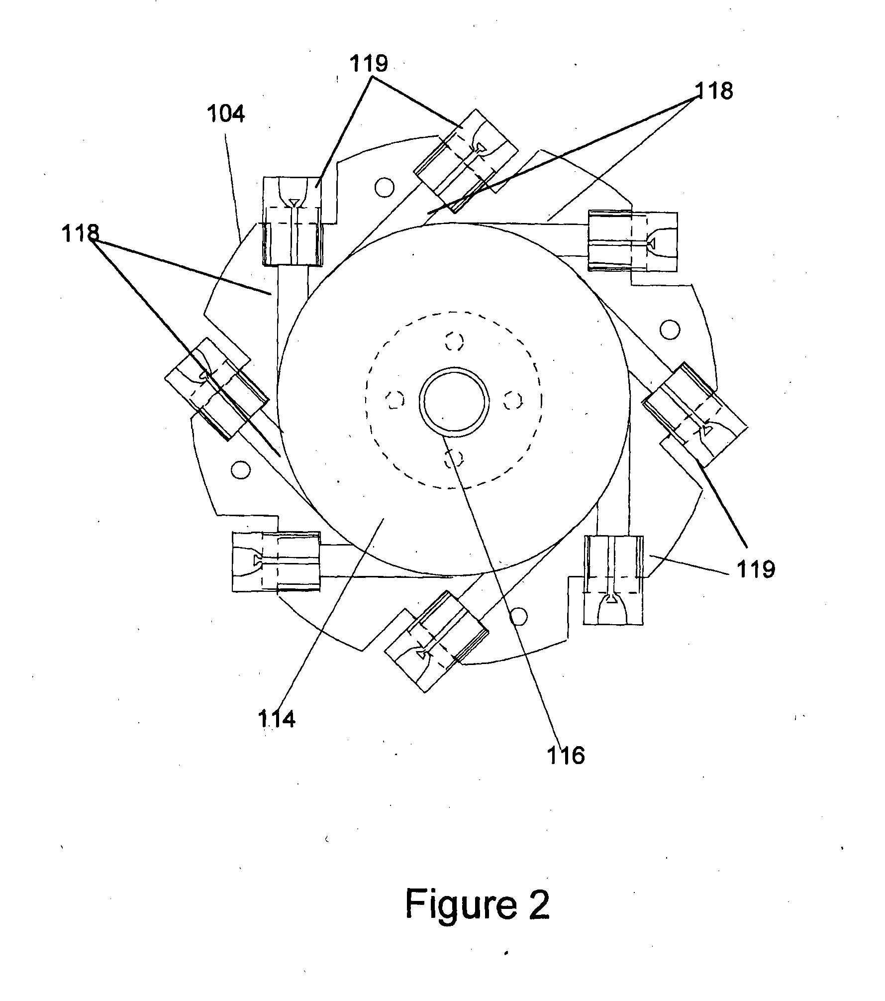
[0027]With reference to FIG. 1 there is illustrated one possible configuration for a rotor assembly 100 according to one embodiment of the present invention. As shown the rotor assembly 100 in this instance includes a rotor mechanism 101 disposed between support plates 1021, 1022. The plates in this example may be coupled together via a set of support rods which are fixed to each plate through apertures 103 thereby retaining the rotor mechanism 101 between the plates 1021, 1022.
[0028]The rotor mechanism 101 in this case includes head 104 and body 105. The head 104 is secured to the body 105 via the use of suitable fasteners inserted through apertures 106 to form a fluid tight seal between the head 104 and body 105. As shown the body 105 includes a passage 107 for receipt of a fluid inlet member 108 for injection of a working fluid into the head 104 of the rotor. The fluid inlet member 108 in this case is inserted into the passage 107 through inlet fixture 109 disposed in plate 1022....
PUM
 Abstract
Description
Claims
Application Information
 - Generate Ideas
- Intellectual Property
- Life Sciences
- Materials
- Tech Scout
- Unparalleled Data Quality
- Higher Quality Content
- 60% Fewer Hallucinations
Browse by: Latest US Patents, China's latest patents, Technical Efficacy Thesaurus, Application Domain, Technology Topic, Popular Technical Reports.
© 2025 PatSnap. All rights reserved.Legal|Privacy policy|Modern Slavery Act Transparency Statement|Sitemap|About US| Contact US: help@patsnap.com