[0034]Reference will now be made in detail to the preferred embodiments of the present invention, examples of which are illustrated in the accompanying drawings. Wherever possible, the same reference numbers are used in the drawings and the description to refer to the same or like parts.
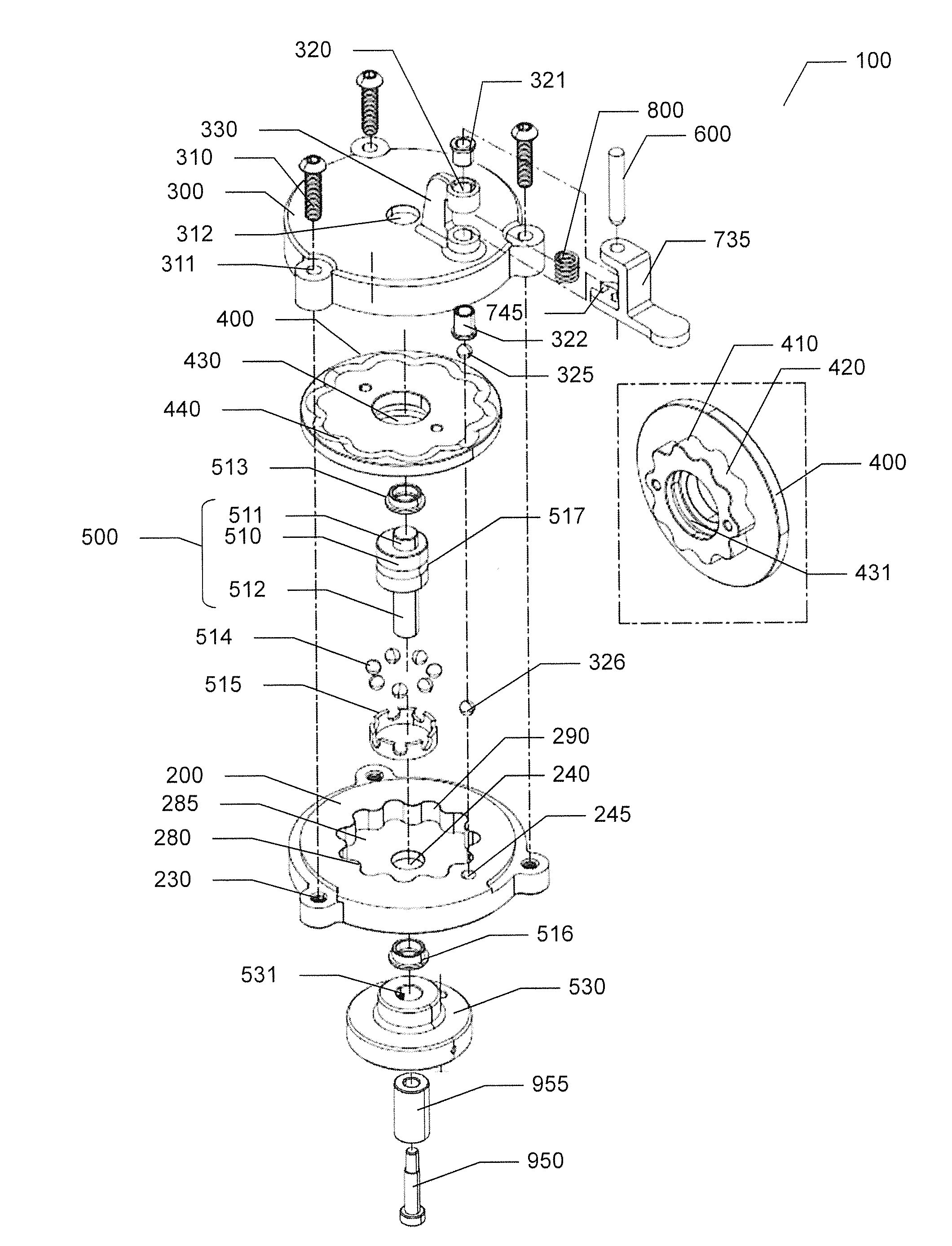
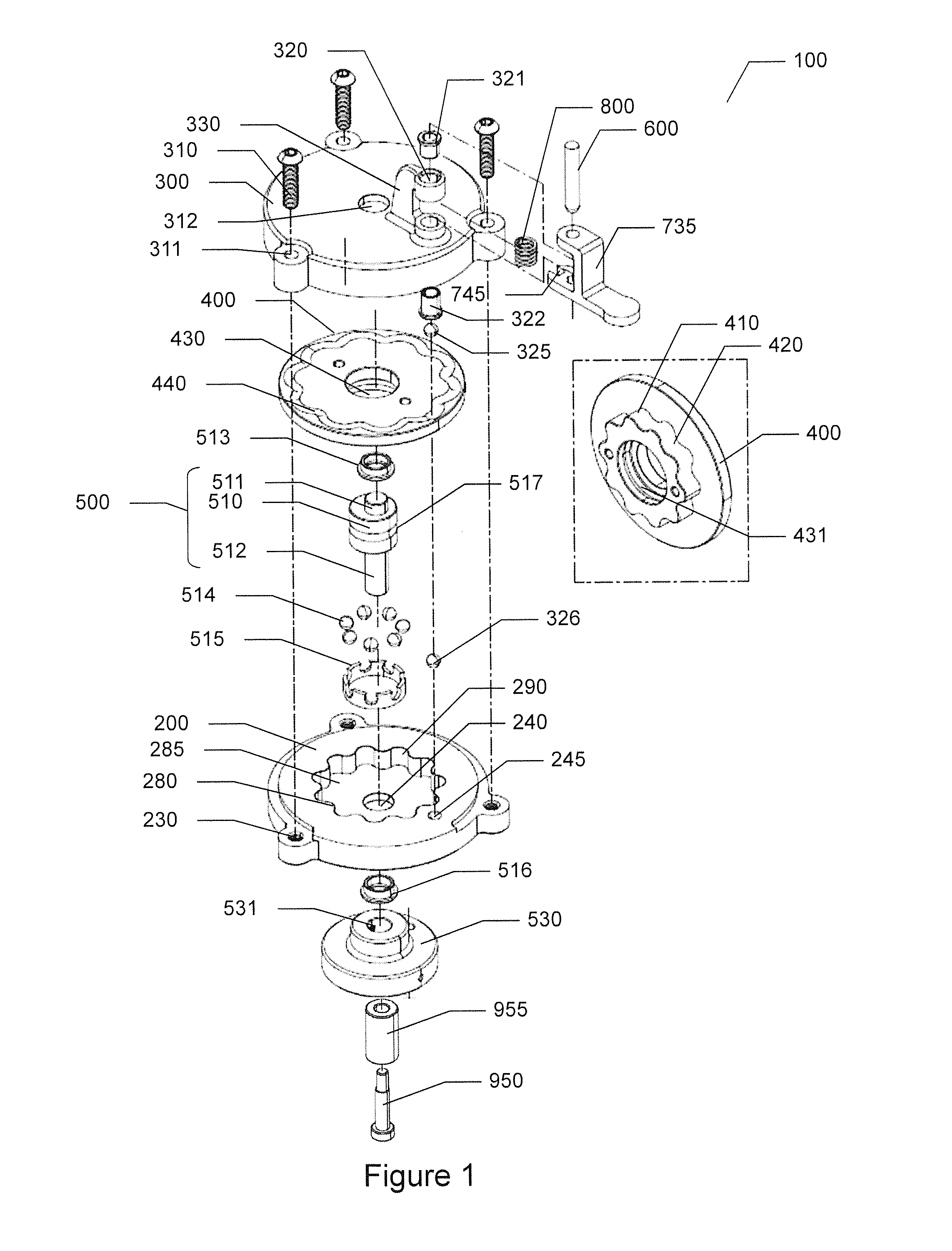
[0035]Refer to FIGS. 1, 2A-2B, and 3A-3B. Note that FIGS. 2B and 3B include a cutaway 301 in the housing cap for clarity in illustrating the epicycloid planet gear 400, cam track 440 and follower pin 600 positioning. The epicycloid planet gear cam, also called the cycloid drive cam, 100 of the present invention comprises a stationary housing 200, a housing cap 300, an epicycloid planet gear, also called a cycloid disc, 400, a driveshaft eccentric 500, and a cam follower pin 600.
[0036]The stationary housing 200 comprises an internal stationary ring gear 285. The epicycloid planet gear 400 and the driveshaft eccentric 500 are assembled inside the stationary housing 200 and the housing cap 300 is assembled to the stationary housing 200 thereby encasing the epicycloid planet gear 400 and the driveshaft eccentric 500 inside the housing cap 300 and the stationary housing 200.
[0037]The driveshaft eccentric 500 is fixed to a driveshaft 955 of a DC motor or hand crank with a driveshaft connector 950 and freely rotates in the eccentric mounting hole 430 of the epicycloid planet gear 400. When the driveshaft 955 turns the driveshaft eccentric 500 will rotate and cause the epicycloid planet gear 400 to rotate around the stationary ring gear 285 in an opposite direction to the driveshaft 955 rotational direction.
[0038]As the epicycloid planet gear 400 rotates, a cam track 440 of the epicycloid planet gear 400 causes the cam follower pin 600 to rise and fall as a spring 800 exerts pressure on an output device 735 to hold the cam follower pin 600 to the cam track 440.
[0039]Since the cam follower pin 600 is press fitted to the output device 735, the output device 735 moves along with the cam follower pin 600.
[0040]The stationary housing 200 comprises a plurality of threaded holes 230, a driveshaft clearance hole 240, and a stationary ring gear 285 comprising a plurality of ring gear lobes 280, and a plurality of ring gear lobe clearances 290.
[0041]In this embodiment of the present invention the housing cap 300 is attached to the stationary housing 200 by inserting threaded fasteners 310 through fastener holes 311 of the housing cap 300 into the threaded holes 230 of the stationary housing 200. In other embodiments of the present invention the housing cap 300 and the stationary housing 200 are assembled using various other methods to attach the housing cap 300 and the stationary housing 200 together.
[0042]The driveshaft clearance hole 240 is disposed in the body of the stationary housing 200 to allow the driveshaft 955 to connect with the driveshaft eccentric 500. The plurality of ring gear lobes 280 and the plurality of ring gear lobe clearances 290 between the ring gear lobes 280 are disposed in the interior of the stationary housing 200 to form the stationary ring gear 285. The ring gear lobes 280 and ring gear lobe clearances 290 engage with cycloid lobes 410 and cycloid lobe clearances 420 of the epicycloid planet gear 400 and allow the epicycloid planet gear 400 to rotate around the interior of the stationary housing 200.
[0043]The housing cap 300 further comprises a cam follower clearance hole 320 and a cam follower support bracket 330.
[0044]Disposed on the top of the housing cap 300 is the cam follower support bracket 330. The cam follower clearance hole 320 in the cam follower support bracket 330 allows the cam follower pin 600 to travel up and down through the cam follower clearance hole 320. An upper sleeve 321 and a lower sleeve 322 are positioned in the cam follower clearance hole 320 to reduce friction during movement of the follower pin 600.
[0045]As the cam follower pin 600 travels up and down an anti-rotation feature 745 on the output device 735 slides along the cam follower support bracket 330 of the housing cap 300. As the output device 735 moves the arms of the anti-rotation feature 745 closely but freely hug the cam follower support bracket 330 and the output device 735 is prevented from rotating.
[0046]Refer to FIGS. 5 and 6A-6C while continuing to refer to FIGS. 1-3B.
[0047]The epicycloid planet gear 400 comprises a plurality of cycloid lobes 410, a plurality of cycloid lobe clearances 420, an eccentric mounting hole 430, and a cam track 440.
[0048]The plurality of cycloid lobes 410 is disposed around the bottom of the epicycloid planet gear 400. Between each cycloid lobe 410 is a cycloid lobe clearance 420. The cycloid lobes 410 and the cycloid lobe clearances 420 engage with the ring gear lobes 280 and ring gear lobe clearances 290 of the stationary ring gear 285 of the stationary housing 200 and allow the epicycloid planet gear 400 to rotate around the interior of the stationary housing 200.
[0049]The eccentric mounting hole 430 is provided to allow the epicycloid planet gear eccentric driver 510 of the driveshaft eccentric 500 to cause rotational movement of the epicycloid planet gear 400 in cycloid drive fashion. It should be noted that the epicycloid planet gear 400 is not attached to the driveshaft eccentric 500 and the epicycloid planet gear eccentric driver 510 is only positioned into the eccentric mounting hole 430 of the epicycloid planet gear 400.
[0050]The cam track 440 is disposed in the top surface of the epicycloid planet gear 400. The cam track 440 comprises a recess pattern around the epicycloid planet gear 400 that gradually increases in depth beneath the top surface of the epicycloid planet gear 400.
[0051]In the embodiment of FIG. 6B at the cam track start 450 the depth of the cam track 440 is at its shallowest depth and at the cam track end 460 the depth of the cam track 400 is at its deepest depth.
[0052]In the embodiment of FIG. 6C the cam track comprises an endless cam track 440 where the cam track 440 gradually increases in depth below the top surface of the epicycloid planet gear 400 before gradually returning to its original start depth at the cam track end which coincides with the cam track start in endless loop fashion.
[0053]The shape or pattern of the cam track 440 is determined by the path generated by a fixed imaginary point atop the epicycloid planet gear 400 as the epicycloid planet gear 400 rotates.
[0054]Refer to FIG. 4 while referring to FIGS. 1-3B and 5-6B.
[0055]When assembled, a follower roller ball 325 positioned under the cam follower pin 600 contacts the cam track 440 and the spring 800 provides pressure downwards on the output device 735 to push the follower roller ball 325 under the cam follower pin 600 down on the cam track 440. As the epicycloid planet gear 400 rotates, the cam track 440 causes the cam follower pin 600, via the follower roller ball 325, to move in relation to the depth of the cam track 440. For example, as the cam track 440 increases in depth the cam follower pin 600, via the follower roller ball 325, lowers and as the cam track 440 decreases in depth the cam follower pin 600 rises.
[0056]A support roller ball 326 is positioned in a support hole 245 in the top surface of the stationary housing 200. The support roller ball 326 is below the vertical position of the follower roller ball 325 and the epicycloid planet gear 400 separates the support roller ball 325 and the follower roller ball 325. As the follower roller ball 325 presses downward on the cam track 440, the support roller ball 326 supports the epicycloid planet gear 400 to prevent shifting or tilting of the epicycloid planet gear 400.
[0057]Additionally, controlling the rotational direction of the driveshaft 955 can affect the movement of the cam follower pin 600. For example, if the driveshaft 955 continues to rotate in one direction the cam follower pin 600 will repeatedly move in relation to the cam track 440 depth pattern over and over again in a cycle. However, if the rotational direction of the driveshaft 955 turns in one direction and then in the opposite direction different movement patterns of the cam follower pin 600 can be achieved. For example, the driveshaft 955 can be made to rotate in one direction until the cam follower pin 600 nears the cam track end 460 and then the driveshaft 955 can be made to rotate in the opposite direction until the cam follower pin 600 nears the cam track start 450. In this way, the rotational direction of the driveshaft 955 can control the position of the cam track 440 thereby controlling the movement of the cam follower pin 600 and the positioning of the output device 735. Furthermore, incremental changes in rotational direction of the driveshaft 955 provides for accurate positioning of the cam follower pin 600.
[0058]The driveshaft eccentric 500 comprises an epicycloid planet gear eccentric driver 510, an upper stem 511, a lower stem 512, and a roller groove 517.
[0059]During assembly the epicycloid planet gear eccentric driver 510 is positioned in the eccentric mounting hole 430 of the epicycloid planet gear 400. It should be noted that the driveshaft eccentric 500 is not attached to the epicycloid planet gear 400 and the epicycloid planet gear eccentric driver 510 freely rotates inside the eccentric mounting hole 430 of the epicycloid planet gear 400.
[0060]The roller groove 517 is disposed around the epicycloid planet gear eccentric driver 510. A roller ball set 514 comprising a plurality of roller balls rests in a ball seat 515. The roller balls of the roller ball set 514 are positioned between the driveshaft eccentric 500 and the eccentric mounting hole 430 and freely rotate in the roller groove 517 and a mounting hole groove 431 inside the eccentric mounting hole 430. The roller ball set 514 reduces friction and improves movement while providing stability for the driveshaft eccentric 500.
[0061]The upper stem 511 extends into a cap sleeve 513 disposed in a cap hole 312 of the housing cap 300. The lower stem 512 extends through a housing sleeve 516 disposed in the driveshaft clearance hole 240 in the stationary housing 200.
[0062]An eccentric driver counterbalance 530 is disposed under the bottom surface of the stationary housing 200 and is fixed to the lower stem 512. For example, the eccentric driver counterbalance 530 is fastened to the lower stem 512 by a set screw 533. The eccentric driver counterbalance 530 provides a counterbalance to the epicycloid planet gear eccentric driver 510 to reduce vibration. The eccentric driver counterbalance 530 is 180 degrees out of phase with the epicycloid planet gear eccentric driver 510 and equal in moment. A counterbalance hole 531 is provided to allow the lower stem 512 of the driveshaft eccentric 500 to connect to a driveshaft 955, for example the driveshaft of the DC motor or hand crank. In this embodiment a driveshaft fastener 950 is utilized to connect the driveshaft 955 to the lower stem 512. In other embodiments the driveshaft 955 comprises a fixed fastener on the driveshaft 955 to connect to the lower stem 512.
[0063]Following is a description of the operation of the epicycloid planet gear cam of the present invention. Refer to all Figures.
[0064]When the driveshaft 950 turns the connected driveshaft eccentric 500 also turns. The epicycloid planet gear eccentric driver 510 in the eccentric mounting hole 430 drives the epicycloid planet gear 400 in an eccentric, cycloidal motion. As the epicycloid planet gear eccentric driver 510 rotates in one direction the eccentric mounting hole 430 (and the epicycloid planet gear 400) rotates in the opposite direction.
[0065]As the epicycloid planet gear 400 rotates, the follower roller ball 325 rides the cam track 440 or encounters the cam track start 450. At the cam track start 450 the cam track 440 is at the shallowest depth, the follower roller ball 325 and the cam follower pin 600 is at its highest point, and the output device 735 is at its most extended position. As the epicycloid planet gear 400 continues to rotate the follower roller ball 325 rides along the cam track 440. As the cam track 440 increase in depth the follower roller ball 325 and the cam follower pin 600 lower and the output device 735 moves inward. As the cam track 440 decreases in depth the follower roller ball 325 and the cam follower pin 600 rise and the output device 735 moves outward.
[0066]By controlling the amount of rotation and the rotational direction of the driveshaft 950, the positioning of the output device 735 can be accurately controlled by positioning the follower roller ball 325 and cam follower pin 600 on the appropriate position on the cam track 440.
[0067]It will be apparent to those skilled in the art that various modifications and variations can be made to the present invention without departing from the scope or spirit of the invention. In view of the foregoing, it is intended that the present invention cover modifications and variations of this invention provided they fall within the scope of the invention and its equivalent.