
CMOS device including molecular storage elements in a via level

Active Publication Date: 2011-02-03
TAIWAN SEMICON MFG CO LTD
View PDF6 Cites 0 Cited by
  • Summary
  • Abstract
  • Description
  • Claims
  • Application Information

AI Technical Summary

Benefits of technology

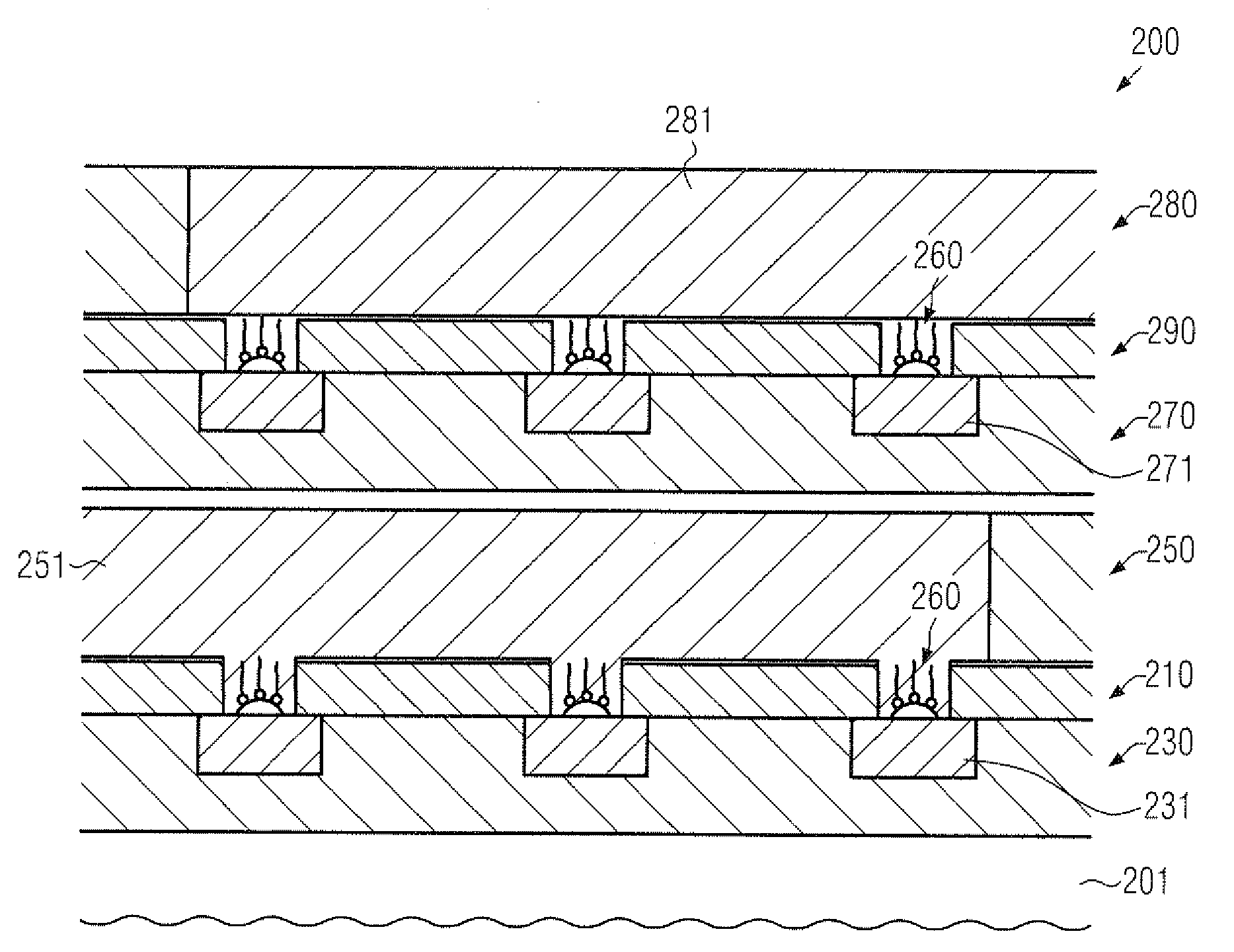
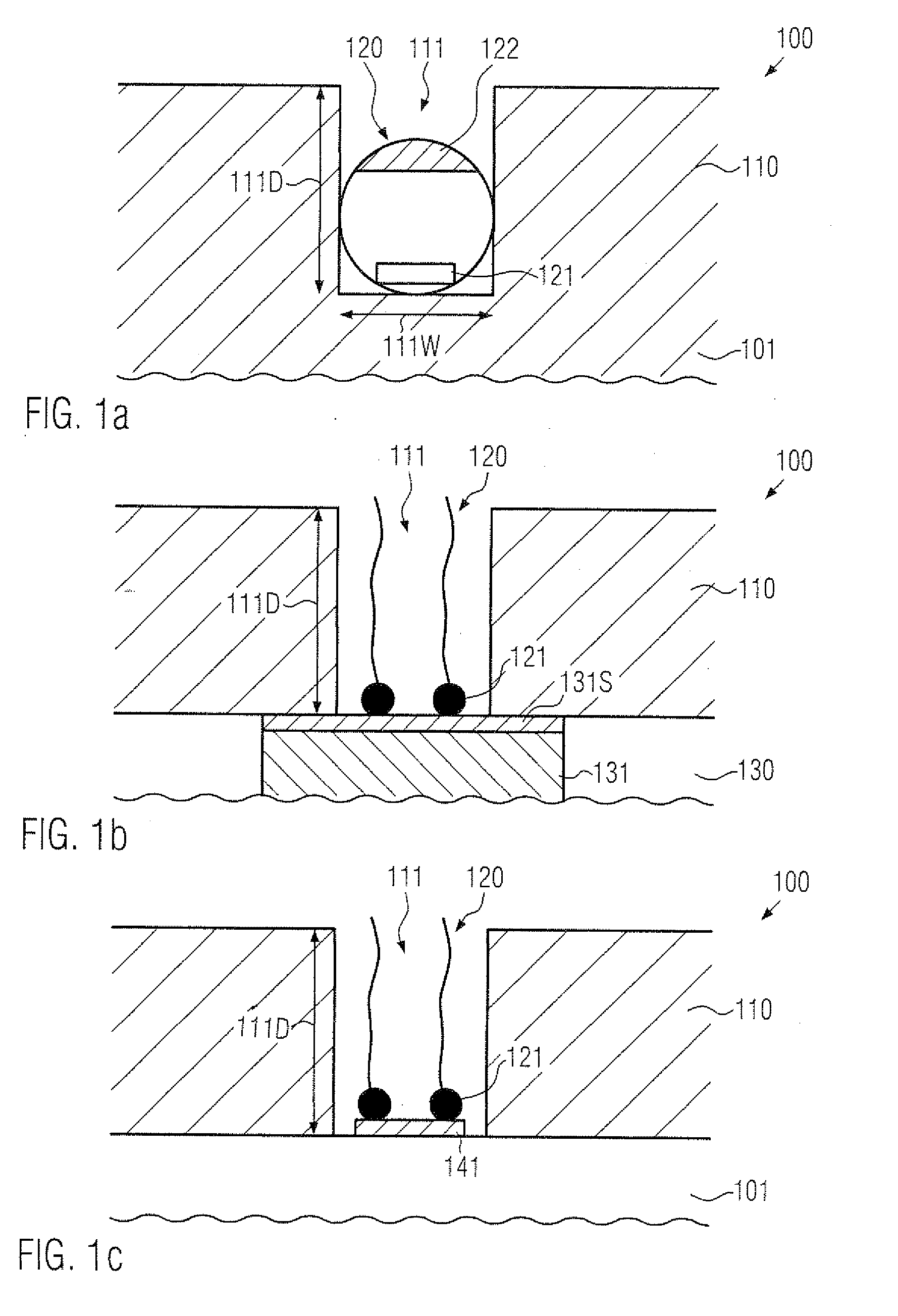
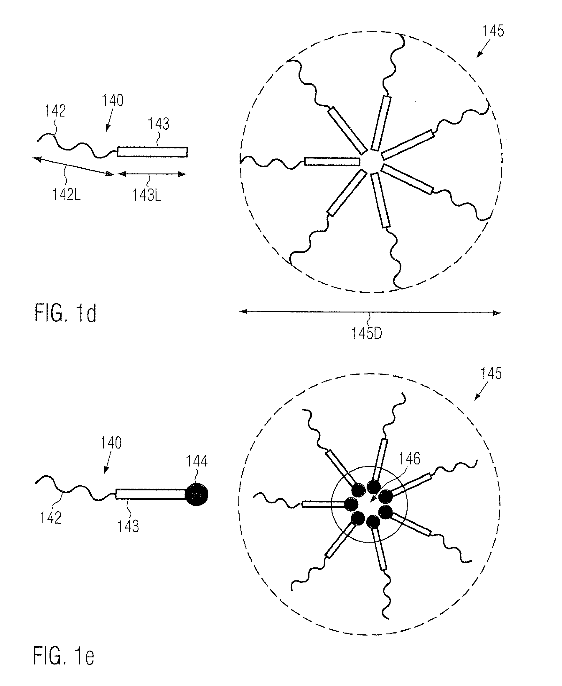
[0010]Generally, the present disclosure relates to integrated circuit devices and manufacturing techniques in which functional molecules, acting as a storage element, may be efficiently applied on the basis of CMOS compatible techniques, thereby enabling the production of efficient integrated circuit devices comprising CMOS components and circuit elements formed on the basis of functional molecules. For this purpose, in some illustrative aspects disclosed herein, the functional molecules may be efficiently adapted in size to the patterning capability of CMOS techniques by using respective openings or vias in a certain device level to accommodate a predefined number of functional molecules. In some aspects, the vias may be formed according to manufacturing strategies as may typically be applied when forming contact levels or metallization systems of sophisticated semiconductor devices so that the corresponding available “capabilities” of patterning and lithography techniques may be efficiently used, while the actual floor space required for a circuit element, such as a memory cell, may be restricted to the via due to the efficient confinement of the functional molecules. Furthermore, appropriate “electrodes” for operatively connecting to the functional molecules may be provided in the form of metal lines and the like, which may also be formed on the basis of manufacturing techniques used during the formation of metallization systems of CMOS devices. Furthermore, since the concept of confining functional molecules to corresponding vias may be applied for a plurality of device levels, a significant overall bit density may be accomplished, for instance in a specified portion of a metallization system, thereby providing significant advantages, independent of the actual lateral dimensions of the corresponding vias.

Problems solved by technology

Hence, the characteristics of the individual transistors significantly affect overall performance of the overall integrated circuit.
Typically, a dynamic RAM cell comprises a storage capacitor and a single transistor, wherein, however, a complex memory management system is required so as to periodically refresh the charge stored in the storage capacitors, which may otherwise be lost due to unavoidable leakage currents.
Although the bit density of dynamic RAM devices may be very high, charge has to be transferred from and to the storage capacitors in combination with periodic refresh pulses, thereby rendering these devices less efficient in terms of speed and power consumption compared to static RAM cells.
With any further device scaling, the “top down” scaling principles of the CMOS technology may encounter severe physical limitations, which may have a significant influence on the overall device configuration and the process techniques.
For example, a further scaling of transistor elements may be extremely difficult on the basis of well-established materials and process techniques which, in the past, have provided complex and efficient integrated circuit devices, which nevertheless may be produced at an acceptable price.
In particular, it may be difficult to further increase the bit density of memory areas since at least one transistor may be required on the basis of advanced memory architectures.
For example, by downsizing the individual storage transistors in combination with reducing the overall size of the storage capacitors, the packing density may be reduced, wherein, however, upon encountering severe limitations with respect to the transistor size, a further downscaling is difficult to achieve.
Moreover, by reducing the size and thus capacity of the storage capacitors, the refreshing of the leakage currents in the storage capacitors has to be performed more frequently, thereby contributing to a higher complexity of the peripheral control circuitry and also contributing to an increased power consumption.
Furthermore a fundamental problem of static and dynamic memory architectures is the volatility of the storage contents since the information is lost upon switching off the supply voltage.
However, although such functional molecules may be readily designed in accordance with specific requirements for, for instance, providing a “molecular switch” and the like for implementing the basic function of a memory element, the provision of an individual memory cell and its addressability are difficult to achieve, in particular when a size of the resulting memory cell is to be obtained that is less than the size of sophisticated semiconductor-based transistor elements.

Method used


Image

  • CMOS device including molecular storage elements in a via level
  • CMOS device including molecular storage elements in a via level
  • CMOS device including molecular storage elements in a via level

Examples


Embodiment Construction

[0025]Various illustrative embodiments of the invention are described below. In the interest of clarity, not all features of an actual implementation are described in this specification. It will of course be appreciated that in the development of any such actual embodiment, numerous implementation-specific decisions must be made to achieve the developers' specific goals, such as compliance with system-related and business-related constraints, which will vary from one implementation to another. Moreover, it will be appreciated that such a development effort might be complex and time-consuming, but would nevertheless be a routine undertaking for those of ordinary skill in the art having the benefit of this disclosure.

[0026]The present subject matter will now be described with reference to the attached figures. Various structures, systems and devices are schematically depicted in the drawings for purposes of explanation only and so as to not obscure the present disclosure with details ...


PUM


Abstract

Memory cells in integrated circuit devices may be formed on the basis of functional molecules which may be positioned within via openings on the basis of appropriate patterning techniques, which may also be used for forming semiconductor-based integrated circuits. Consequently, memory cells may be formed on a “molecular” level without requiring extremely sophisticated patterning regimes, such as electron beam lithography and the like.

Description

BACKGROUND OF THE INVENTION[0001]1. Field of the Invention[0002]Generally, the present disclosure relates to integrated circuits, and, more particularly, to the manufacture of complex circuits including memory areas, for instance in the form of a cache memory of a CPU, with superior bit density.[0003]2. Description of the Related Art[0004]Presently, complex integrated circuits comprise a large number of semiconductor-based circuit elements on a given chip area according to a specified circuit layout, wherein transistor elements represent one of the dominant semiconductor elements in the integrated circuits. Hence, the characteristics of the individual transistors significantly affect overall performance of the overall integrated circuit. Generally, a plurality of process technologies are currently practiced, wherein, for complex circuitry, such as microprocessors, storage chips, ASICs (application specific ICs) and the like, CMOS technology is currently one of the most promising app...

Claims


Application Information

Patent Timeline
IPC IPC(8): H01L23/532H01L21/768
CPCG11C13/0014G11C13/0016H01L51/0591H01L51/0003H01L27/281H10K19/201H10K71/12H10K10/50
Inventor KRONHOLZ, STEPHANLENSKI, MARKUSRICHTER, RALF
Owner TAIWAN SEMICON MFG CO LTD
Learn More