Photon counting x-ray detector

Active Publication Date: 2015-08-20
KONINKLJIJKE PHILIPS NV
View PDF1 Cites 11 Cited by
  • Summary
  • Abstract
  • Description
  • Claims
  • Application Information

AI Technical Summary

Benefits of technology

[0003]It is an object of the invention to provide means that allow for a

Problems solved by technology

A problem of this approach is that the behavior of the detector may drift ov

Method used


Image

  • Photon counting x-ray detector
  • Photon counting x-ray detector
  • Photon counting x-ray detector

Examples


Embodiment Construction

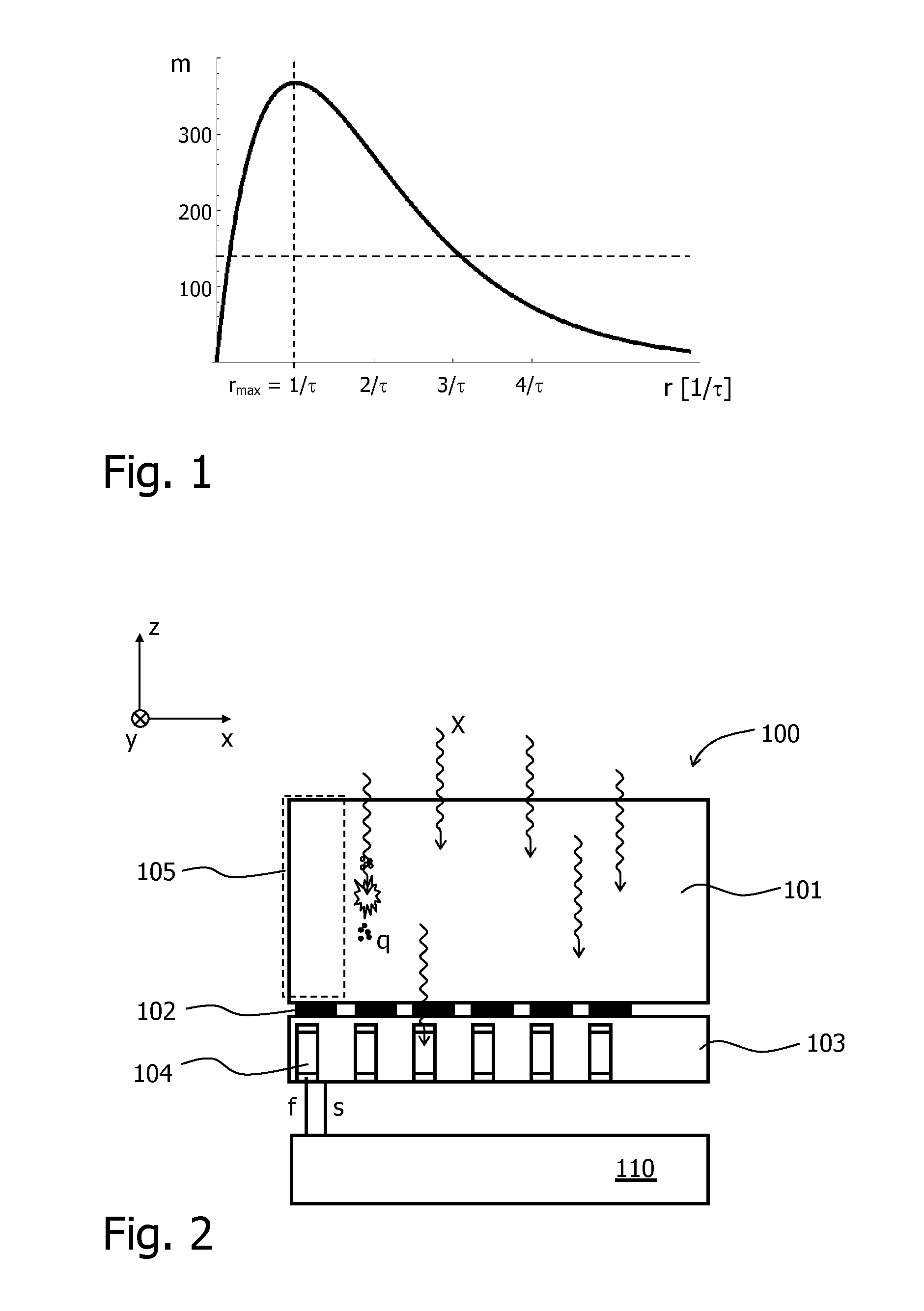
[0045]Photon counting spectral CT faces the challenges of having to cope with very high X-ray flux rates, conditions under which even the best counting detectors build from

[0046]CdTe or CZT behave in an intrinsically non-linear way due to pulse-pileup and dead-time effects. Depending on the detector electronics the behavior of the detectors can be modeled by the paralyzable or non-paralyzable detector behavior. In both cases the deviations from linearity are small as long as the rates remain smaller than the inverse deadtime but behave very differently around or above that level.

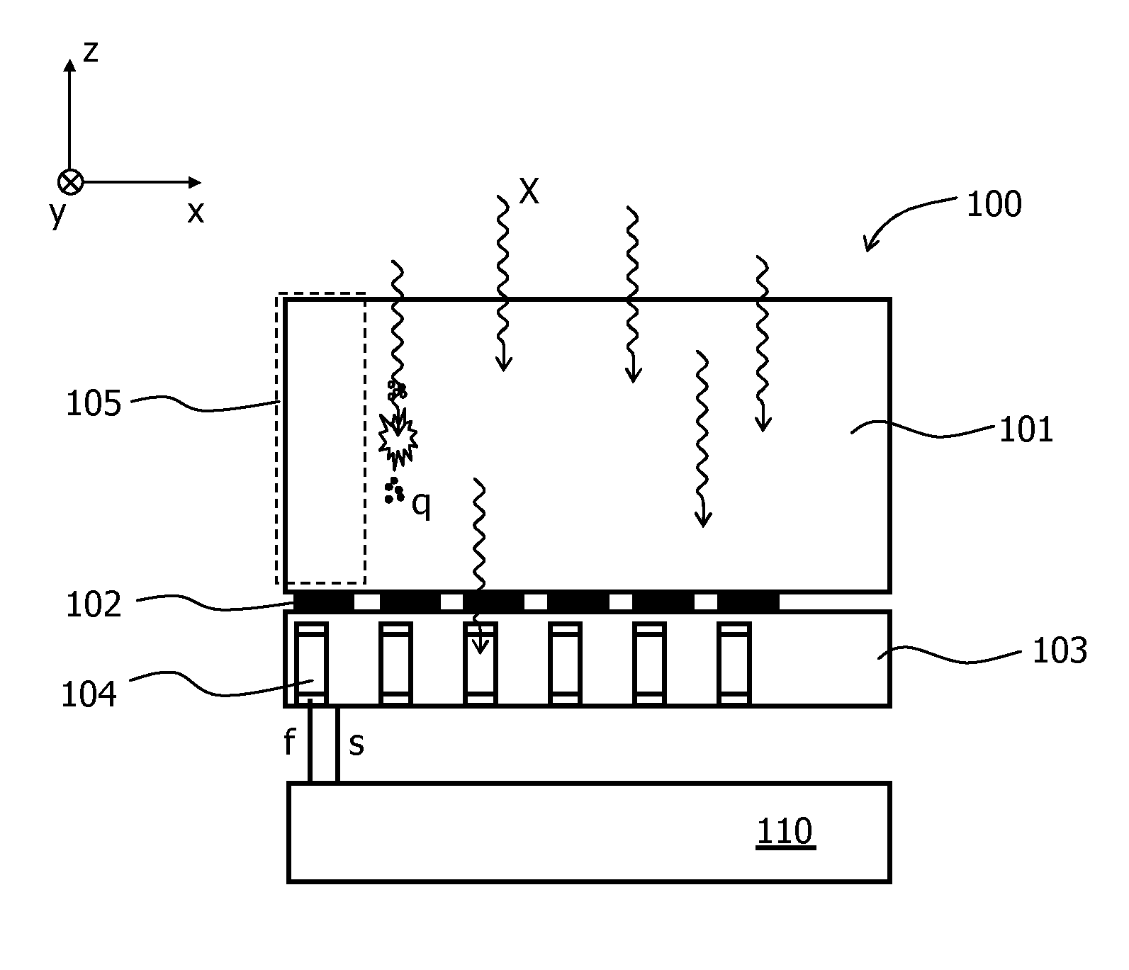
[0047]For example, the output count rate m of a paralyzable detector is a function of the input count rate r (number of incident X-ray photons per time) and a parameter τ which is related to the width of the pulses generated by the detector. It is theoretically given by the formula

m=rexp(−r·τ).

[0048]FIG. 1 shows the curve corresponding to this formula, which has a maximum at rmax=1 / τ. For one measurement of ...


PUM


Abstract

The invention relates to a method and an X-ray detector (100) for detecting incident X-ray photons (X). The X-ray detector (100) comprises at least one sensor unit (105) in which X-ray photons (X) are converted into sensor signals (s) and at least one flux sensor (104) for generating a flux signal (f) related to the flux of photons (X). The sensor signals (s) are corrected based on the flux signal (f). In a preferred embodiment, the sensor signals (s) represent a spectrally resolved pulse counting. The flux sensor (104) may be integrated into an ASIC (103) that is coupled to the sensor unit (105).

Description

FIELD OF THE INVENTION[0001]The invention relates to an X-ray detector and a method for the detection of incident X-ray photons. Moreover, it relates to an imaging system comprising such an X-ray detector.BACKGROUND OF THE INVENTION[0002]The U.S. Pat. No. 7,268,354 B2 discloses an X-ray detector with a plurality of detector elements for counting incident X-ray photons. In order to improve the linearity of the detector elements, correction factors are determined in advance. A problem of this approach is that the behavior of the detector may drift over time such that the determined correction factors may become inappropriate.SUMMARY OF THE INVENTION[0003]It is an object of the invention to provide means that allow for a more accurate determination of X-radiation and an improved dynamic range.[0004]This object is achieved by an X-ray detector according to claim 1, a method according to claim 2, and an imaging system according to claim 3. Preferred embodiments are disclosed in the depen...

Claims


Application Information

Patent Timeline
IPC IPC(8): G01T1/24G01N23/04
CPCG01T1/171G01N23/046G01T1/247G01T1/248
Inventor ROESSL, EWALDHEINER, DAERRSTEADMAN BOOKER, ROGER
Owner KONINKLJIJKE PHILIPS NV
Why Eureka
Try Eureka