
Magnetic Retention System

a magnetic and retaining system technology, applied in the field of eyeglass holder, can solve the problems of awkward and uncomfortable wearing, unattractive, awkward and uncomfortable metal and mechanical holder in the pocket,

Inactive Publication Date: 2015-08-20
LEVESQUE DAVID J
View PDF3 Cites 36 Cited by
  • Summary
  • Abstract
  • Description
  • Claims
  • Application Information

AI Technical Summary

Benefits of technology

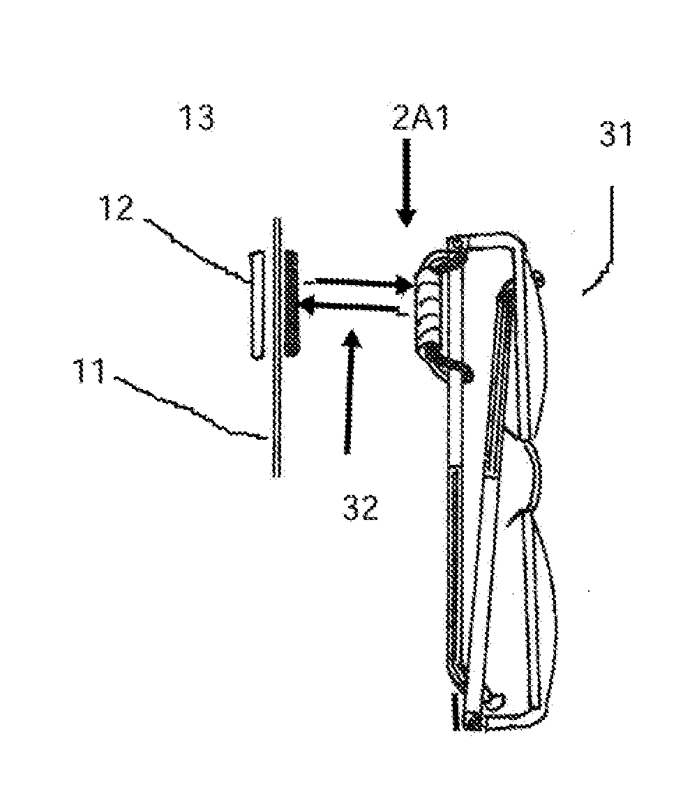
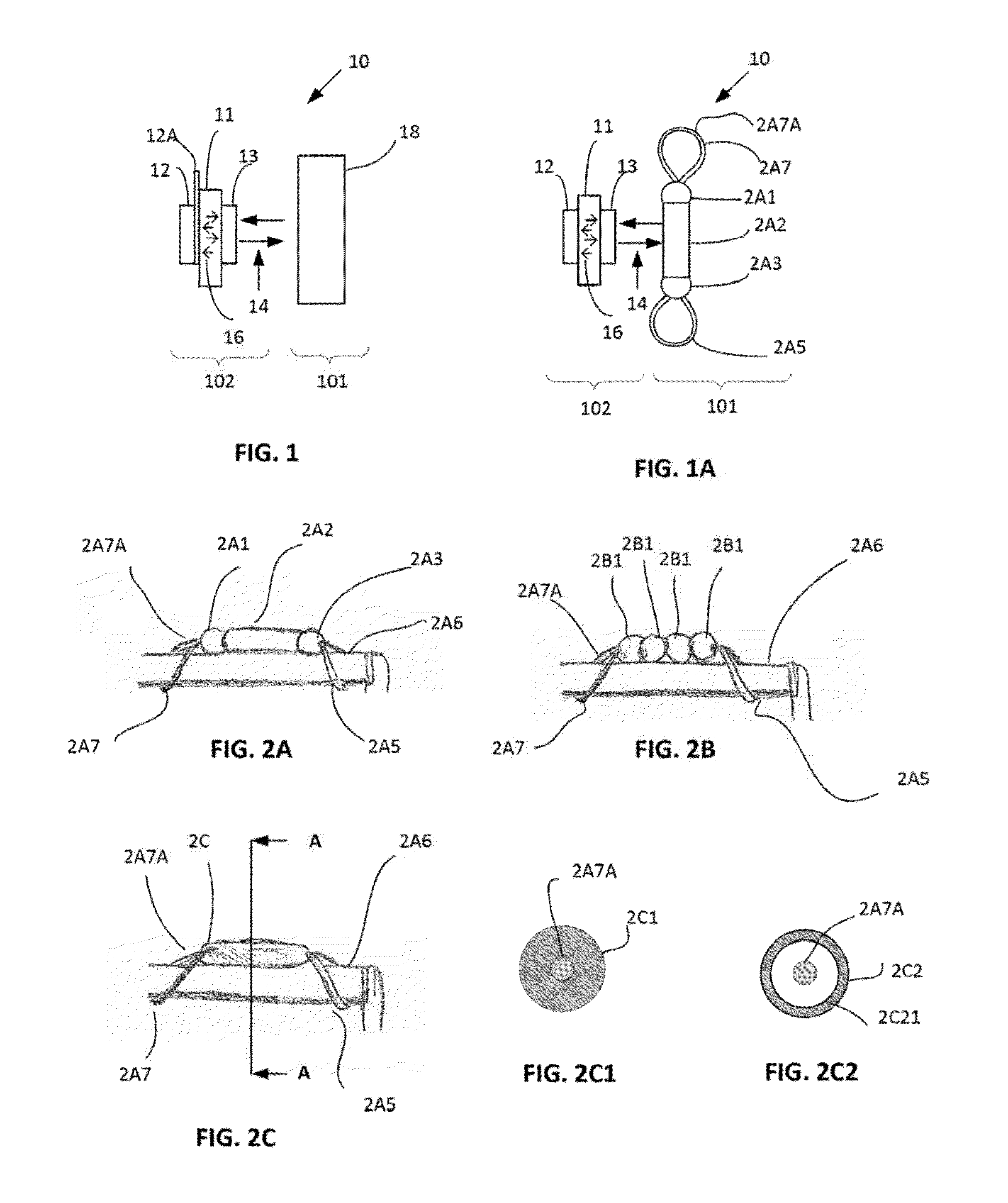
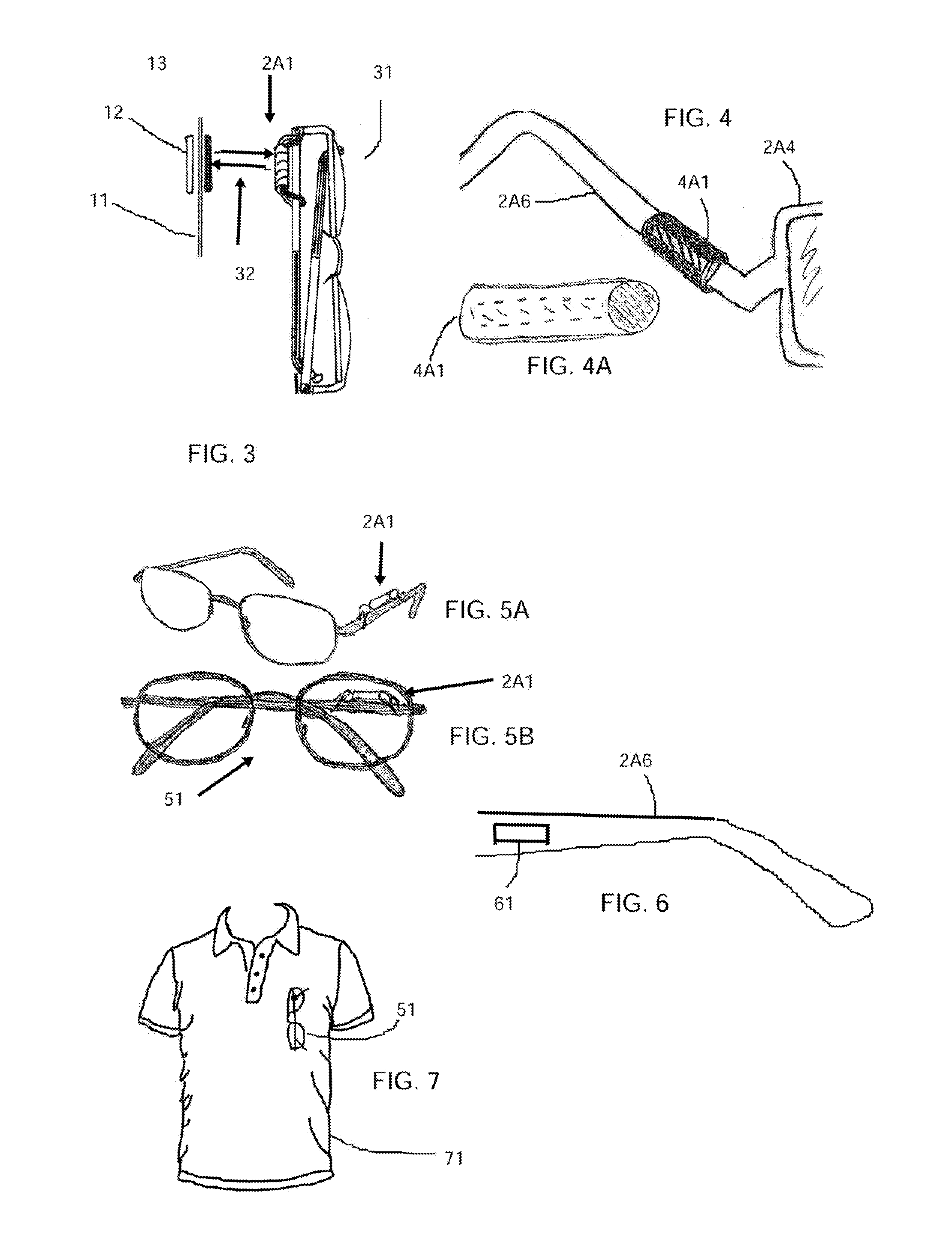
The invention allows users to easily attach and detach eyewear from anywhere on any type of clothing. It consists of a base unit made up of neodymium magnets placed on the clothes, and a piece of fashion jewelry made from metal that attaches to the eyewear's temples using magnetic attraction. This allows the eyewear to be securely held on during most daily activities.

Problems solved by technology

They may hang them around their neck where they bounce against their chest, they may put them in a pocket and have them fall out or they may put them in a place where they can get damaged.
Especially when individuals go to bed at night, they may put down their eyeglasses somewhere and not recall where the next morning when they need them.
These are unsatisfactory for many reasons.
Namely, when the glasses are being held they are awkward and uncomfortable, especially when the wearer is in motion.
If the chain or cord is kept attached to the glasses, it is very uncomfortable while wearing.
If you take the chain off and on it is a nuisance and a storage problem, especially if you need the glasses to find and install the temple attachments.
Metal and mechanical holders that are fitted in the pocket are awkward and unattractive and tend to pull the pocket down because of the weight of the glasses and the attachment.
This solution is undesirable because it damages the fabric to which it is attached.
Adhesive attachment is not satisfactory because the adhesive always leaves a trace that attracts and accumulates dirt.
This solution is undesirable because it requires the user to look at the holding loop in order to insert the eyeglass temple into the holding loop, thus requiring a certain amount of dexterity and visual acuity not always possessed by a user, for example an aged or arthritic user; similar to threading the eye of a needle, a potentially dangerous proposition if driving or the like.
In addition, this solution does not address the needs of an active user in that the temple can easily fall out of the loop holder if the user is jumping or running.

Method used


Image

  • Magnetic Retention System
  • Magnetic Retention System
  • Magnetic Retention System

Examples


Embodiment Construction

[0031]The following brief definition of terms shall apply throughout the application:

[0032]The term “outer” or “outside” refers to a direction away from a user, while the term “inner” or “inside” refers to a direction towards a user;

[0033]The term “comprising” means including but not limited, to, and should be interpreted in the manner it is typically used in the patent context;

[0034]The term “magnetic communication” means magnetically attracted or magnetically affixed;

[0035]The phrases “in one embodiment,”“according to one embodiment,” and the like generally mean that the particular feature, structure, or characteristic following the phrase may be included in at least one embodiment of the present invention, and may be included in more than one embodiment of the present invention (importantly, such phrases do not necessarily refer to the same embodiment);

[0036]If the specification describes something as “exemplary” or an “example,” it should be understood that refers to a non-exclu...


PUM


Abstract

A magnetic retention system (MRS) for magnetically holding parts, such as an eyewear temple part is provided. The MRS includes a positioning subassembly having a ferromagnetic backing plate and a neodymium magnet, wherein the neodymium magnet is adaptable to magnetic communication with the backing plate. The MRS also includes a retention subassembly having a ferromagnetic retainer adaptable to magnetic communication with the neodymium magnet.

Description

CROSS-REFERENCE TO RELATED APPLICATIONS[0001]The present application is related to, claims the earliest available effective filing date(s) from (e.g., claims earliest available priority dates for other than provisional patent applications; claims benefits under 35 USC §119(e) for provisional patent applications), and incorporates by reference in its entirety all subject matter of the following listed application(s) (the “Related Applications”) to the extent such subject matter is not inconsistent herewith; the present application also claims the earliest available effective filing date(s) from, and also incorporates by reference in its entirety all subject matter of any and all parent, grandparent, great-grandparent, etc. applications of the Related Application(s) to the extent such subject matter is not inconsistent herewith:[0002]1. United States provisional patent application 61 / 940,473 entitled “Invisible Magnetic Eyeglass Holder”, naming David J. Levesque as inventor, filed 16 ...

Claims


Application Information

Patent Timeline
IPC IPC(8): G02C3/00G02C11/00G02C5/14
CPCG02C3/04G02C11/00G02C2200/02Y10T24/314Y10T24/32
Inventor LEVESQUE, DAVID J.
Owner LEVESQUE DAVID J
Learn More