Projection system and projection method thereof

a projection system and projection method technology, applied in the field of projection systems and projection methods thereof, can solve problems such as waste of manpower and tim

Inactive Publication Date: 2015-08-20
CORETRONIC
View PDF4 Cites 13 Cited by
  • Summary
  • Abstract
  • Description
  • Claims
  • Application Information

AI Technical Summary

Problems solved by technology

However, quality of the projected image has to be sacrificed, and additional devices have to be used to assist calibrating the combined image each time when the projection image combination is performed, which results in a waste of manpower and time.

Method used


Image

  • Projection system and projection method thereof
  • Projection system and projection method thereof
  • Projection system and projection method thereof

Examples


Embodiment Construction

[0045]In the following detailed description of the preferred embodiments, reference is made to the accompanying drawings which form a part hereof, and in which are shown by way of illustration specific embodiments in which the invention may be practiced. In this regard, directional terminology, such as “top,”“bottom,”“front,”“back,” etc., is used with reference to the orientation of the Figure(s) being described. The components of the invention can be positioned in a number of different orientations.

[0046]As such, the directional terminology is used for purposes of illustration and is in no way limiting. On the other hand, the drawings are only schematic and the sizes of components may be exaggerated for clarity. It is to be understood that other embodiments may be utilized and structural changes may be made without departing from the scope of the invention. Also, it is to be understood that the phraseology and terminology used herein are for the purpose of description and should no...


PUM


Abstract

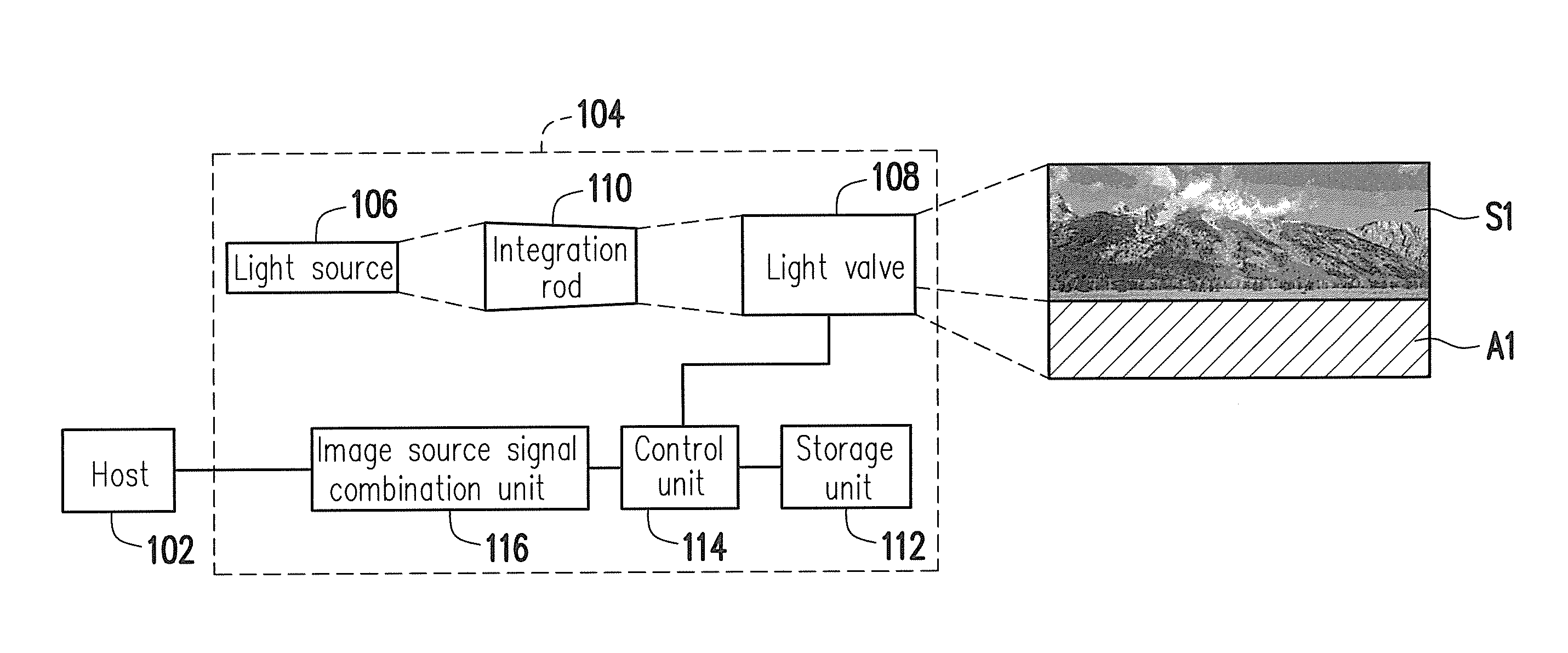
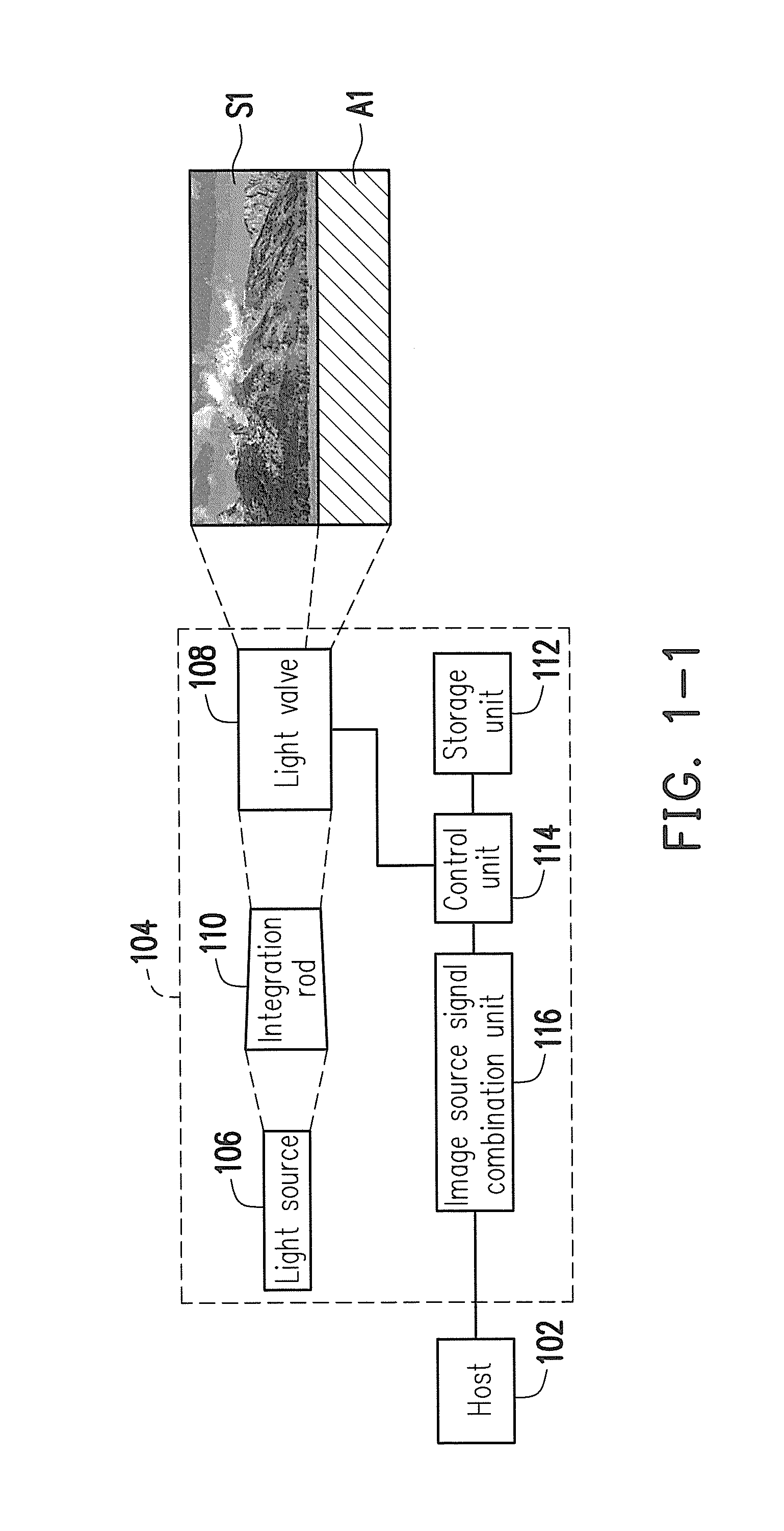
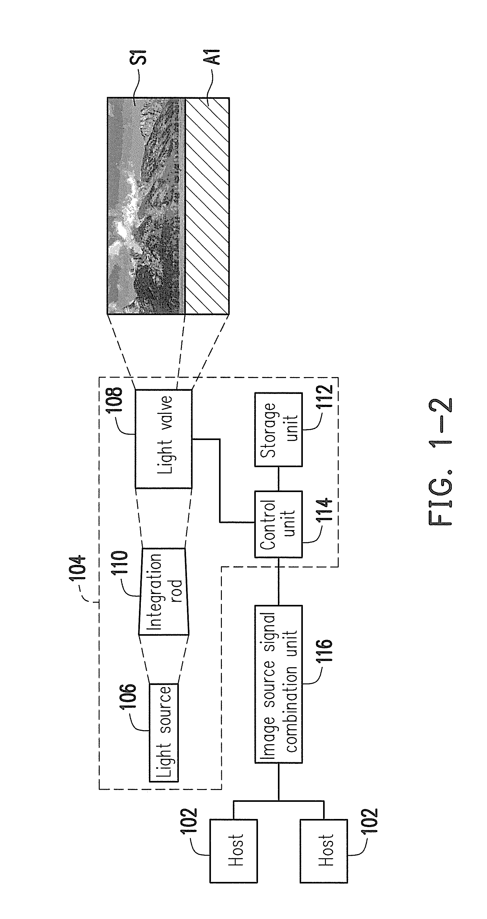
A projection system and a projection method thereof are provided. A plurality of image source signals is combined into a combination image signal. A host is instructed to provide a plurality of the projection ratios corresponding to the image source signals according to extended display identification data. An image source signal combination unit combines the projection ratios corresponding to the image source signals to form a combination projection ratio corresponding to the combination image signal. A light valve is set to a mode corresponding to the combination projection ratio. The illumination beam is converted to an image beam according to the combination image signal.

Description

CROSS-REFERENCE TO RELATED APPLICATION[0001]This application claims the priority benefit of Taiwan application Ser. No. 103105541, filed on Feb. 19, 2014. The entirety of the above-mentioned patent application is hereby incorporated by reference herein and made a part of this specification.BACKGROUNDTechnical Field[0002]The invention relates to a display apparatus. Particularly, the invention relates to a projection system and a projection method thereofRelated Art[0003]Presently, two or more than two projectors are generally used to implement ultrawide screen (such as 16:6) projection in a combination manner, and a transfer box is additionally provided to divide an image signal, and the divided image signals are respectively transmitted to the projectors to implement projection image combination. Since images projected by the projectors used for projection image combination may have differences in color temperature or brightness, etc., one of the projectors is taken as an adjustmen...

Claims


Application Information

Patent Timeline
Patent Type & Authority Applications(United States)
IPC IPC(8): H04N9/31G06F3/042G03B21/60G03B21/00G03B21/20
CPCH04N9/3197G03B21/005G06F3/0421G03B21/60G03B21/208G09G3/001H04N5/7416G06F3/03542H04N9/3185H04N9/3188G03B21/10G03B21/26G03B37/00G03B2206/00
Inventor TSAI, WEN-WEILU, TUNG-YICHANG, CHUN-CHINCHEN, SHUN-TAIJAO, KUN-LIANG
Owner CORETRONIC
Why Eureka
Try Eureka