

Anti-smudge body, display device, input device, and electronic device
a display device and anti-smudge technology, applied in the direction of instruments, transportation and packaging, synthetic resin layered products, etc., can solve the problems of fingerprints adhering to the display screen and deteriorating the visibility of the display screen
- Summary
- Abstract
- Description
- Claims
- Application Information
AI Technical Summary
Benefits of technology
Problems solved by technology
Method used
Image

Examples
first embodiment
1. First Embodiment
[Configuration of Anti-Smudge Substrate]
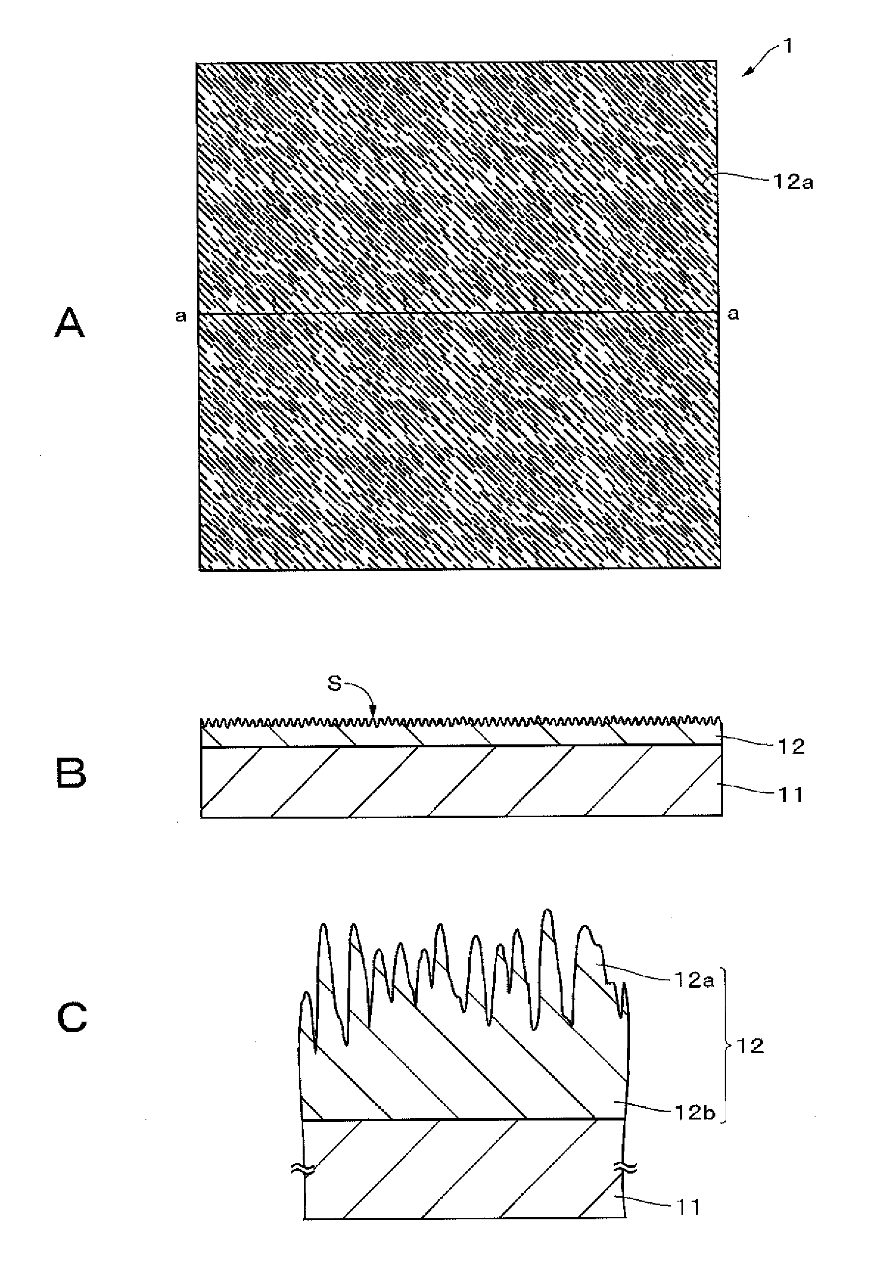
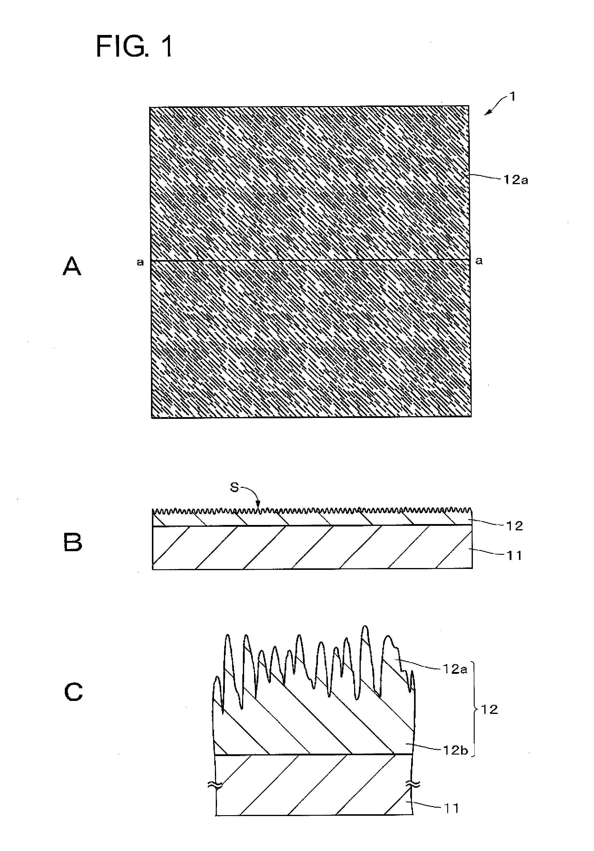
[0063]FIG. 1A is a plan view illustrating an anti-smudge substrate according to a first embodiment of the present technique. FIG. 1B is a cross-sectional view taken along line a-a shown in FIG. 1A. FIG. 1C is an enlarged cross-sectional view representing part of FIG. 1B. The anti-smudge substrate (anti-smudge body) has a fingerprint resistant surface (anti-smudge surface) S having an anti-fingerprint function. This fingerprint resistant surface S contains a compound having a specific molecular structure described later and has a fine irregular structure thereon. Therefore, fingerprints adhering to the fingerprint resistant surface S spread spontaneously and are likely to become less noticeable. In addition, fingerprints adhering to the fingerprint resistant surface S can be made less noticeable by rubbing the fingerprints with, for example, a finger to spread them thinly. The fingerprint resistant surface S has shape fluctua...
first modification
(First Modification)
[0147]FIG. 7A is a cross-sectional view illustrating an example of a configuration of an anti-smudge substrate according to a first modification. As shown in FIG. 7A, this anti-smudge substrate is different from the anti-smudge substrate according to the first embodiment in that an anchor layer 13 provided between the substrate 11 and the anti-smudge layer 12 is further included. When the anchor layer 13 provided between the substrate 11 and the anti-smudge layer 12 is included as described above, the adhesion between the substrate 11 and the anti-smudge layer 12 can be improved. A plurality of structure bodies 12a may be formed by providing a fine irregular structure on the surface of the anchor layer 13 and forming an anti-smudge layer 12 so as to conform to the irregular structure.
[0148]The material of the anchor layer 13 used can be selected from, for example, a wide variety of known natural macromolecular resins and synthetic macromolecular resins. For examp...
second modification
(Second Modification)
[0150]FIG. 7B is a cross-sectional view illustrating an example of a configuration of an anti-smudge substrate according to a second modification. As shown in FIG. 7B, this anti-smudge substrate is different from the anti-smudge substrate according to the first embodiment in that a hard coating layer 14 provided between the substrate 11 and the anti-smudge layer 12 is further included. It is particularly preferable to provide the hard coating layer 14 when the substrate 11 used is a resin substrate such as a plastic film. When the hard coating layer 14 is included between the substrate 11 and the anti-smudge layer 12 as described above, practical properties (such as durability and pencil hardness) can be improved. A plurality of structure bodies 12a may be formed by providing a fine irregular structure on the surface of the hard coating layer 14 and forming an anti-smudge layer 12 so as to conform to the irregular structure.
[0151]The material of the usable hard ...
PUM
| Property | Measurement | Unit |
|---|---|---|
| Mean roughness | aaaaa | aaaaa |
| Mean roughness | aaaaa | aaaaa |
| Structure | aaaaa | aaaaa |
Abstract
Description
Claims
Application Information