
Ozone generating apparatus

a technology of generating apparatus and ozone, which is applied in the direction of ozone preparation, ozone preparation by electrical discharge, and energy-based chemical/physical/physico-chemical processes. it can solve the problems of difficulty in further achieve the effect of improving the yield of ozon

Active Publication Date: 2015-08-27
KK TOSHIBA
View PDF1 Cites 1 Cited by
  • Summary
  • Abstract
  • Description
  • Claims
  • Application Information

AI Technical Summary

Benefits of technology

The present invention relates to an ozone generating apparatus that can improve the yield of ozone by using a discharge gap length of less than 0.6 mm. The apparatus can maintain a constant discharge gap length in a longitudinal direction, even at a reduced length of 0.4 mm. This results in a higher yield of ozone compared to previous generators that had a fixed discharge gap length. The technical effect of this invention is an improved production of ozone.

Problems solved by technology

Due to this, it has been difficult to further improve the yield of ozone.

Method used


Image

  • Ozone generating apparatus
  • Ozone generating apparatus
  • Ozone generating apparatus

Examples


Embodiment Construction

[0079]The following describes an embodiment with reference to the drawings.

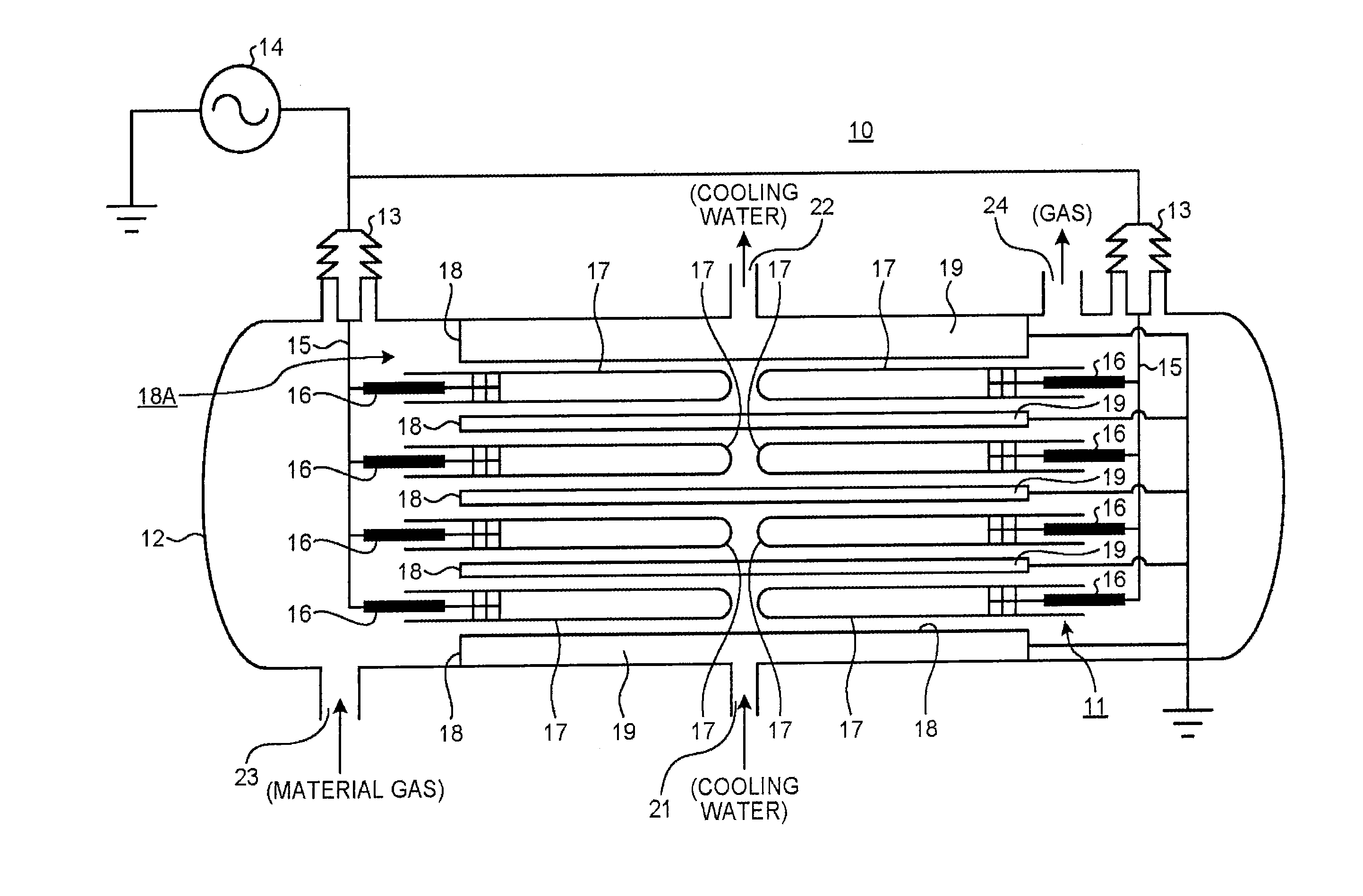
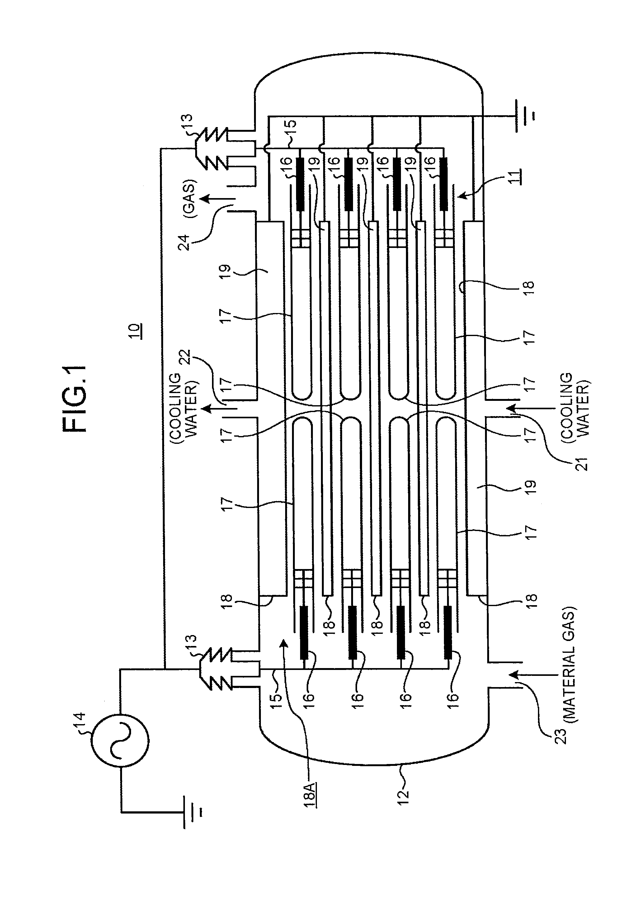
[0080]FIG. 1 is an overview sectional view of an ozone generating apparatus according to the embodiment.

[0081]An ozone generating apparatus 10 according to the embodiment is configured as a dielectric barrier discharge ozone generating apparatus.

[0082]The ozone generating apparatus 10 roughly includes an ozone generating apparatus main body 11, a storage container 12 that stores therein the ozone generating apparatus main body 11 in airtight state, and a high-voltage power supply (high-voltage AC power supply) 14 that supplies electric power for generating ozone to the ozone generating apparatus main body 11 in the storage container 12 via a high-tension insulator 13.

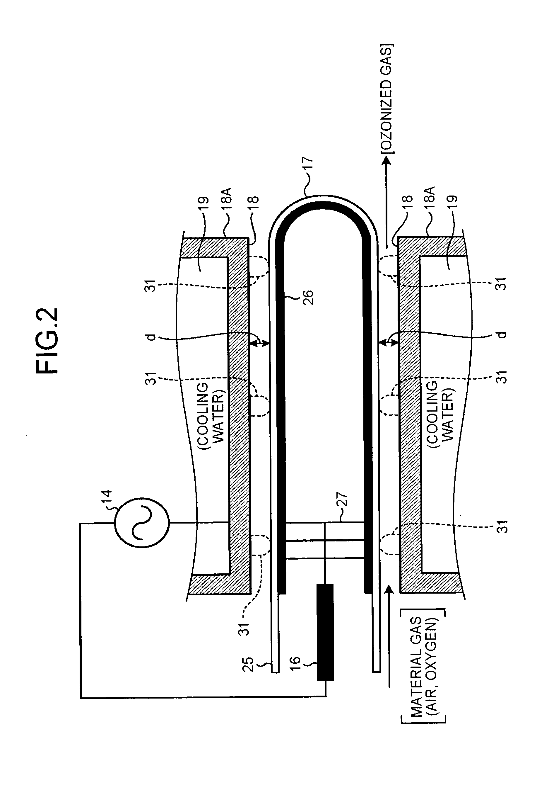
[0083]The ozone generating apparatus main body 11 in the storage container 12 includes a plurality of dielectric electrodes 17 and a cylindrical metal electrode 18 made of stainless steel arranged therein. The electric power for generating ozone ...


PUM

PropertyMeasurementUnit
discharge gap lengthaaaaaaaaaa
pressureaaaaaaaaaa
discharge gap lengthaaaaaaaaaa

Abstract

An ozone generating apparatus includes a cylindrical high-voltage electrode and a coaxially arranged cylindrical low-voltage electrode. A predetermined high voltage is applied between the high-voltage and low-voltage electrodes via a dielectric substance to cause discharge generating ozone, the discharge gap length being 0.3 to 0.5 mm. One of the low-voltage and high-voltage electrodes is a metal electrode and the other a dielectric electrode. A projection group including plural done shape projections, arranged on same circumference of the metal electrode, is arranged on an inner peripheral surface of the metal electrode to hold the metal electrode coaxial with the dielectric electrode while keeping the discharge gap length. The projection group is arranged at a center portion in a longitudinal direction of the discharging space positioned away from both ends of the discharging space by a predetermined distance L3 satisfying, 0.0≦L3 / L≦0.1, L being length of the discharging space.

Description

FIELD[0001]Embodiments of the present invention relate to an ozone generating apparatus.BACKGROUND[0002]Ozone generating apparatuses generally include a dielectric electrode and a metal electrode arranged in an airtight container. A spacer for forming a discharge gap is interposed between the dielectric electrode and the metal electrode. A conductive film is arranged on an inner face of the dielectric electrode.[0003]In such an ozone generating apparatus, material gas introduced into the airtight container from a gas inlet flows through the discharge gap formed between the dielectric electrode and the metal electrode. The material gas that has flowed through the discharge gap is then discharged from a gas outlet.[0004]In parallel with the introduction of the material gas, an AC high voltage is applied between the dielectric electrode and the metal electrode from a high-voltage power supply via a fuse and a high-voltage power supply terminal.[0005]When the AC high voltage is applied,...

Claims


Application Information

Patent Timeline
Patent Type & Authority Applications(United States)
IPC IPC(8): C01B13/11
CPCC01B13/115C01B13/11H01T23/00C01B2201/22C01B2201/32
Inventor TAKAHASHI, RYOICHIMURATA, TAKAAKINODA, KAZUHIKOKUBO, KIE
Owner KK TOSHIBA
Learn More